Totallyamaha RX-1 Expert X Install
|
|
|
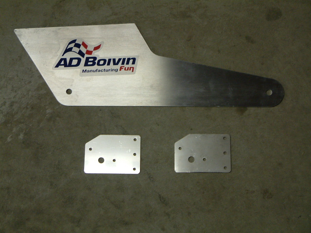
Before beginning the installation, Totallyamaha recommends that you thoroughly read the installation package provided with your Expert X, Be sure you understand the mathematics and all of the layout procedures described. Take your time with the layout, it is very critical that your new suspension be mounted parallel to the tunnel and perpendicular to the drive shaft. (If any of the information provided below conflicts with the installation package provided by AD Boivin, use the their information ) Look through the parts that are provided and make sure you are not missing any mounting hardware. (Click to see pic)
Click Image to Enlarge
|
Click Image to Enlarge
|
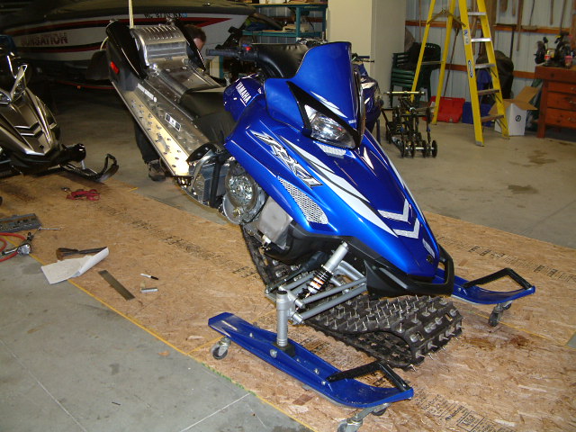
Before unbolting the rear skid, remove the side panels to gain access to the front suspensions bolts.Now you can remove your pro-action skid frame by slightly elevating the rear of the sled so the track is about 2" off the ground. Using a 17 mm and 19 mm wrench loosen the rear shaft slightly. Take a 14 mm socket and ratchet and release the track tension, be sure to count the turns equally off the rear adjusters. (This will aid you in slipping the stock suspension back through the track.) Now remove the (6) 14mm bolts from the tunnel and the skid will fall to the floor. Then remove the 2 rear suspension brackets with a 14 mm wrench (4 additional 14mm bolts). At this point it would be helpful to remove your seat. You will need to unplug the tail light power cable on the throttle side of the seat. Pull up the edge of the seat to expose the wire and unplug the harness to the tail light. Remove exhaust caps with a 5 mm Allen wrench (3 screws) One at 12 o'clock, one at 5 o'clock and one at 7 o'clock on each cap. Next remove the two Phillips head screw below your tail light lens and remove the exhaust grid in the rear of the seat. Once the grid is removed 2 gold hooks with 10 mm nuts that hold the seat in place should be exposed. Remove those 10 mm nuts and lift the seat while pushing the hooks through the retainer clips. Finally slide your seat from front to rear and remove the seat from sled. |
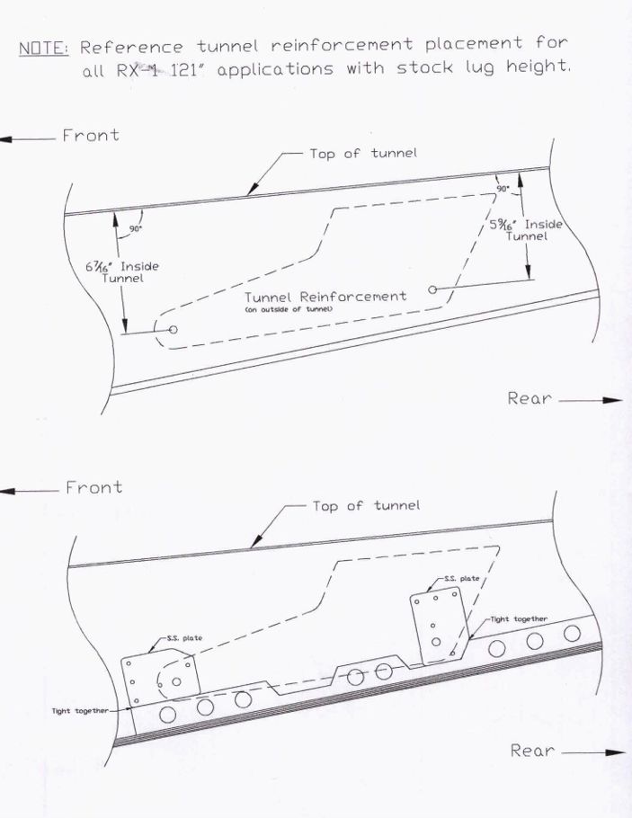
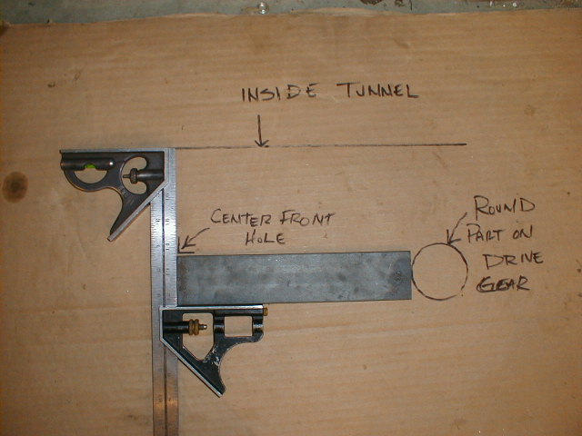
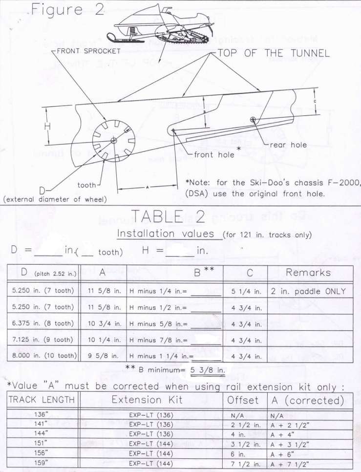
| With the
charts provided (Fig 2) determine your drive cog diameter and the number of
drive teeth. Our drive cog Diameter. was approximately 7 1/8" with 9 tooth
pitch. Our "A" Dimension was 10 1/4" (Center of
drive to 1st hole). The "H" Dimension was not measured because the "B"
& "C" Dimension were given to us by AD Bovine as shown at top left pic. "B"
is 6 7/16 and "C" is 5 9/16" from inside top of the tunnel.
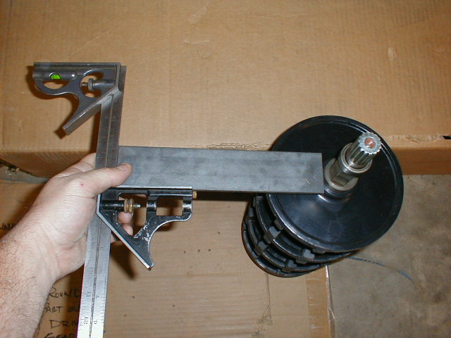
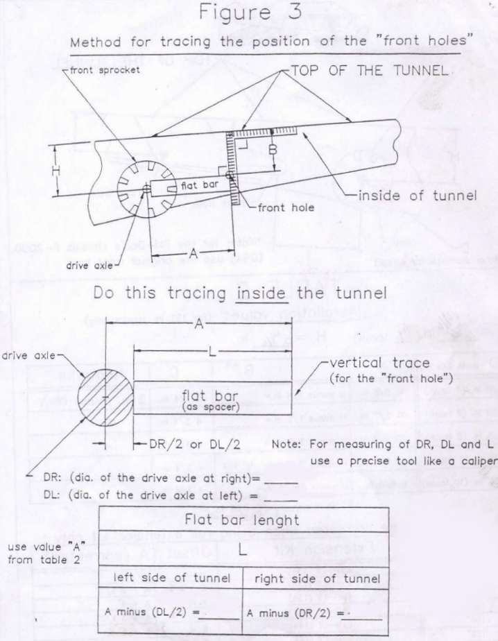
Using Fig 3 of your installation guide, you will need to calculate the dimension from the collar on the drive shaft to the 1st hole "L" ( We took "A" Dimension of 10 1/4" minus 1 5/8" Diameter Collar to get "L" Dimension of 9 7/16"). Then cut a flat bar to the "L" Dimension that will aid in scribing your 1st hole center. See pics to the right to help explain procedure. |
Click Image to Enlarge |
|
Click Image to Enlarge
|
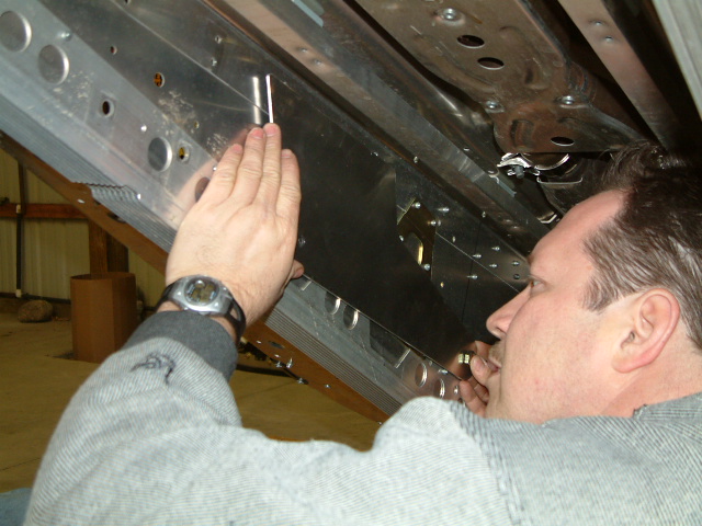
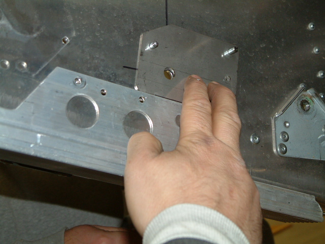
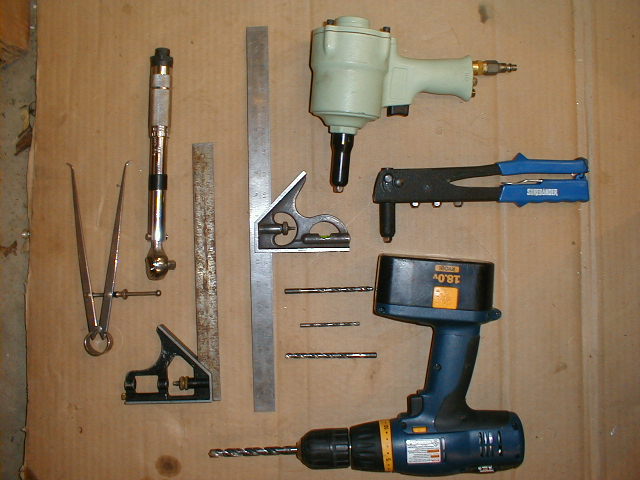
With all of your dimensions and the tools shown in pic above, layout your 1st hole locations on both sides of the tunnel. Make sure your hole are directly across from one another to assure the Expert X will be parallel and straight in the tunnel. |
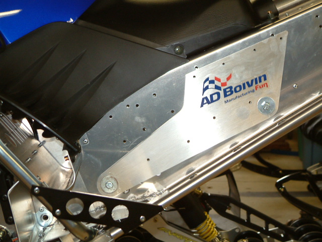
| Before drilling any holes, carefully place the Expert X side plates against the tunnel in their respective places (See Lower Left Pic). Locate and remove any rivets that will prevent the main mounting plates from sitting flat on the outside of the tunnel surface. Remove the middle mount bracket for the stock suspension as shown above.
|
Click Image to Enlarge |
|
Click Image to Enlarge
|
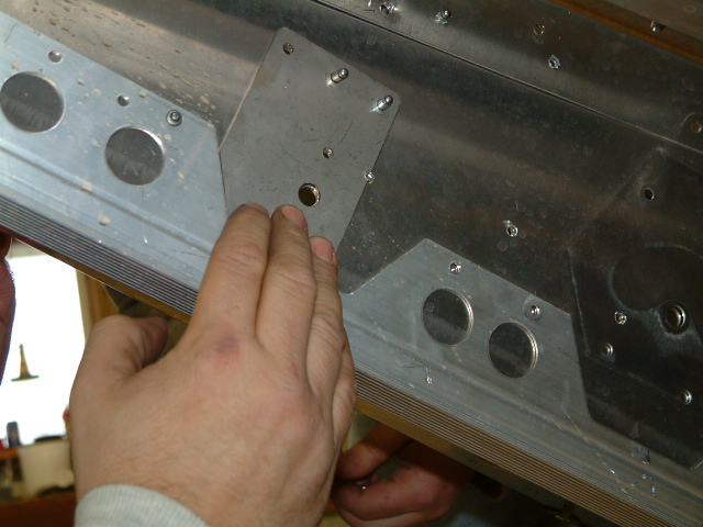
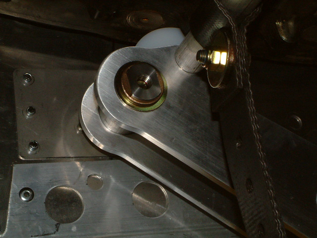
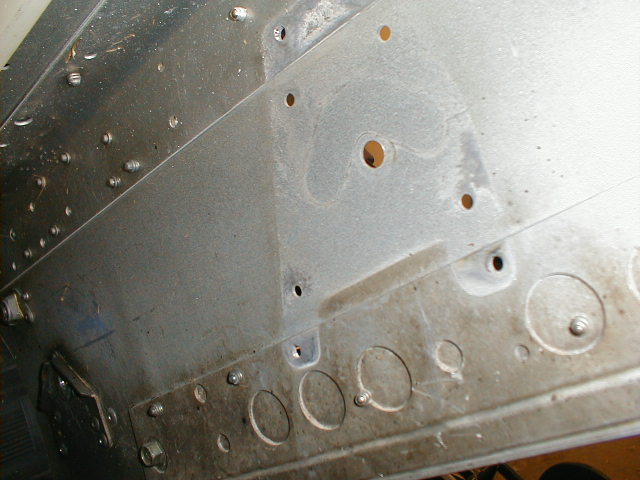
From the inside of the tunnel, center punch and drill out the front most holes using a 25/64 drill. Using the same size bolts as supplied, temporarily mount the side plates through the front hole and rotate the rear of the plate to the 5 9/16" dimension to the rear hole, center punch and drill using a 25/64 drill. |
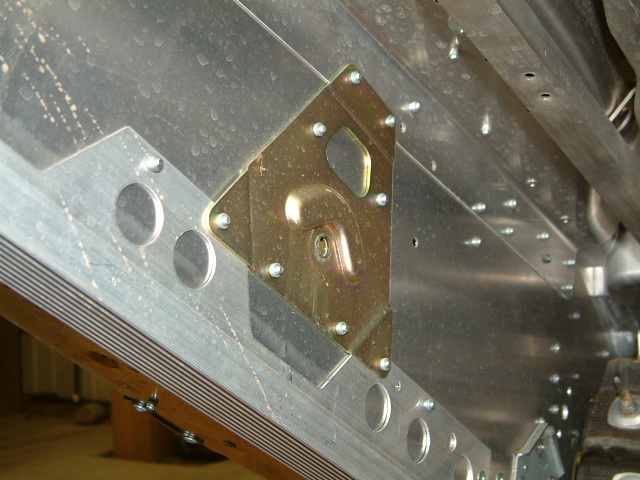
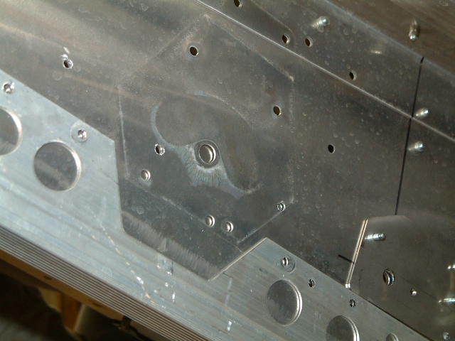
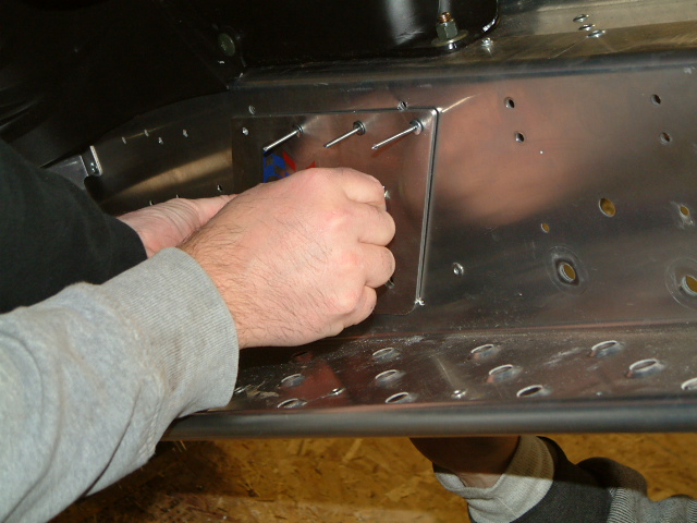
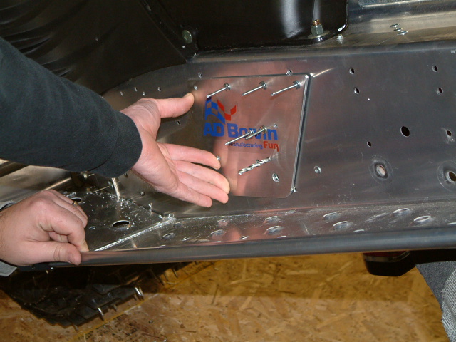
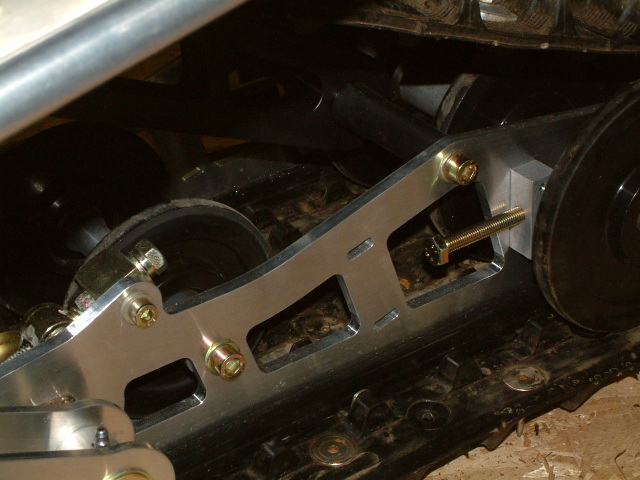
| Temporarily bolt your side plates onto tunnel using the holes you just drilled. Locate and mark evenly the rivet holes along the top edge of the side plates approximately 3/4" down and starting about 3/4"- 1" from each edge, spacing the center two evenly for looks. Pop Rivet the plates to the tunnel with at least 4 rivets. Remove your temporary bolts and position your inner reinforcing backer plates as shown (Right). If you make an error, it can take a fair while to fix. You must make sure at least 2 rivets on each plate fasten through, backer, tunnel and outside main plates. Using your temporary bolts to hold backing plates and side plates in place, drill through all materials and pop rivet. See pic for detail. Make sure at least 8 rivets are used in each side plate. |
Click Image to Enlarge |
|
Click Image to Enlarge
|
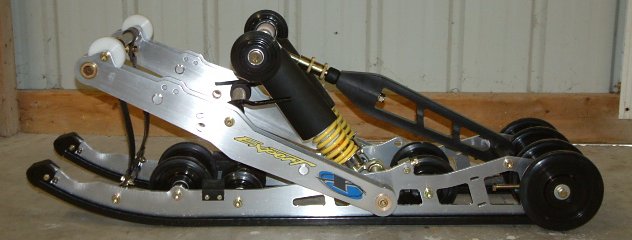
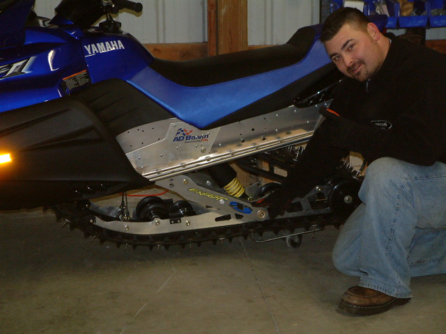
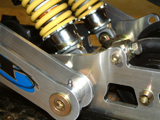
Once your side mounting plates and reinforcing backers are riveted and secured properly, you may take the Expert X skid and slip it between the track into its position. Make sure you do not have the softness adjuster (18mm nut) on the shaft that connects to the softness bar (Big Black Plastic Link Bar) in place when installing the skid. |
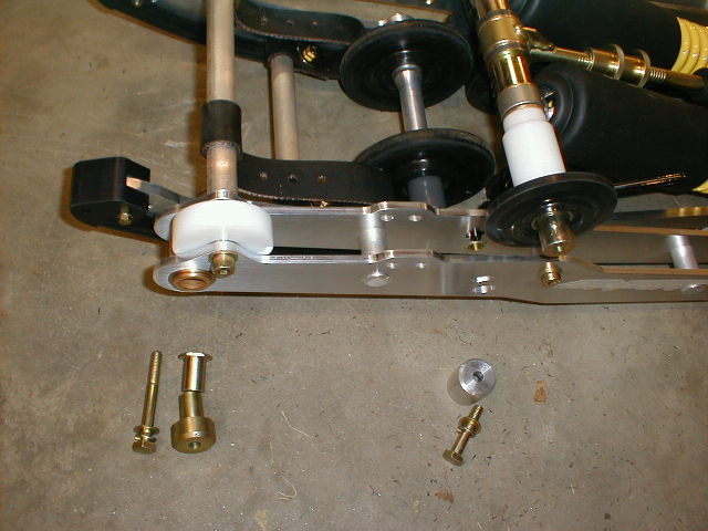
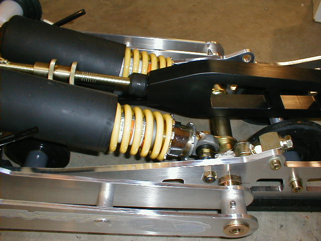
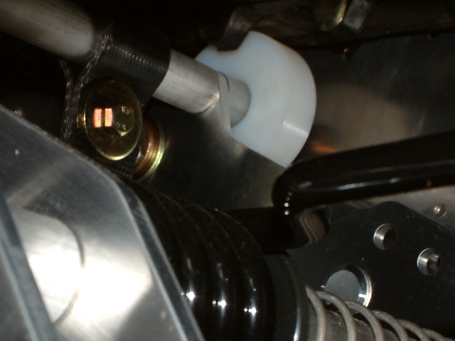
| Take the supplied
hardware shown in the upper image at the left. Slip the inner nut bushing
and outer spacer bushing on to the front (upper) swing arm on both sides. Lift
the front swing arm up and align with your new front mounting holes. Holding
the back side of the inner nut bushing, slide the
front bolts through and hand tighten both sides. See Left Pic. Slide the alum spacers over the rear upper mount/idler shaft on both sides and swing the idler shaft into place and align with the new rear holes. Slide rear bolts through and hand tighten both sides. Torque all four bolts to 38 ft lbs. |
Click Image to Enlarge |
|
Click Image to Enlarge
|
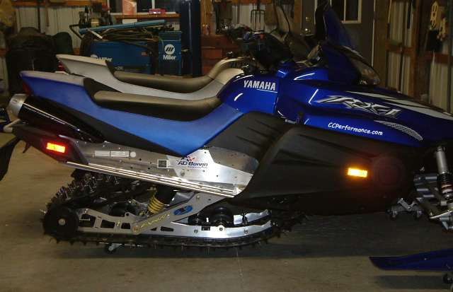
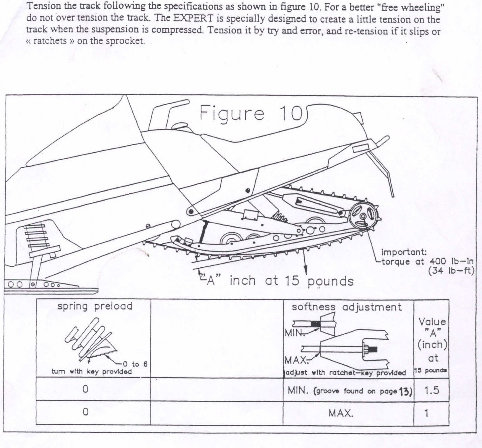
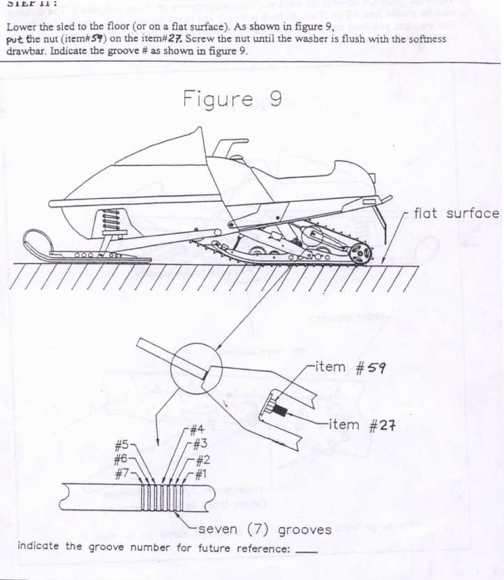
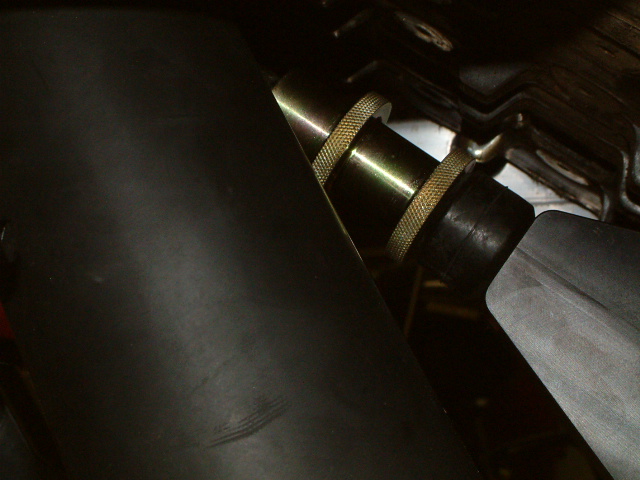
Finally install the 18 MM softness nut and set at desired setting (Fig. 9). You might have to lift the suspension or lower sled to floor to get the nut started. Align track and set track tension by adjusting the rear axle bolts (18mm). Be sure to loosen the rear axle prior to setting track tension and tighten after alignment and track tension is achieved. Approximately 1 1/2" gap at 15 lbs is the proper track tension. See instructions (Fig. 10). Reinstall seat in reverse order as stated above and you are now ready to " Hit the Moguls". |
|
|
|
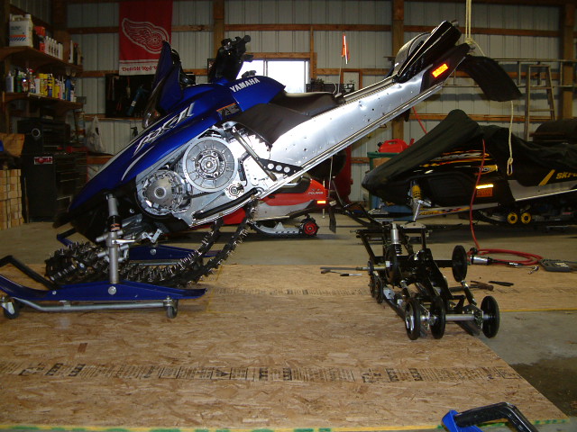
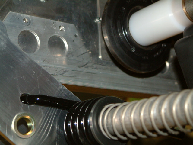
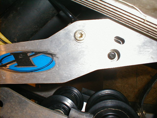
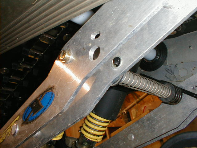
| Special Note: If you
have done the install correctly you will have at least 3/8" gap when
the track is under tension from upper arm plastic protector to the track.
(see Fig. 8 or pic above)
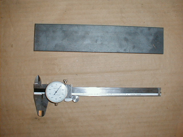
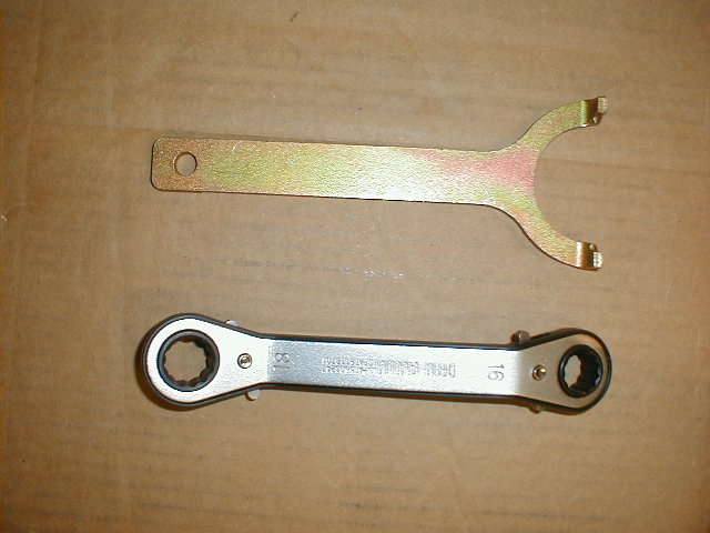
Pictures to the right are some of the tools that will be needed to install the Expert X. |
Click Image to Enlarge |
|
Click Image to Enlarge
|
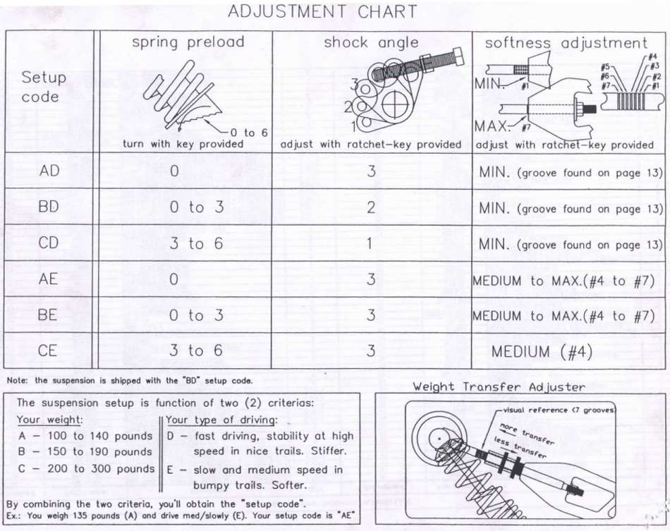
Using the tools shown in the pic to the left, will be required to set up your Expert X to the riding style and weight you prefer. See manual or additional info below. Note: Make sure you set your overload springs to the brass bushed holes in the swing arm. Most likely they will be shipped and set in the top slot hole above the brass bushing. See Pics to the left. Also be sure to Red loctite (#272) all mounting fasteners once you are happy with your installation..and Torque to 400 in-lbs. |
|
Below you will find additional information and pics to help you adjust your Expert X. This is taken from the installation guide.
Click Image to Enlarge
|
|
|
Below you will find additional information to help you with your Expert X hole layout. This is also taken from the installation guide.
Click Image to Enlarge |
|
CCPerformance.com & Totallyamaha.com would like to thank the Siejutt family for their hospitality and patience while making this installation and shoot-out possible.
Totallyamaha is not responsible for any damages that these modifications may cause to your vehicle; any modifications are your responsibility if you choose to do so. We are providing information ONLY. Some of these modifications may VOID your warranty and that is your responsibility to look into. The Totallyamaha users have passed along most of the information found on this site. If you have any questions or concerns about anything on this site talk to your dealer before using any of the information. Totallyamaha will not be liable for any damages or personal injury from any modification performed from this site.
Please let us know if you have anything to add to this page to help out other Yamaha owners. For addition to this page Email webmaster@totallyamaha.com
![]()

