WARN
424 SELECT INSTALLATION INSTRUCTIONS
Caution
-Do not switch to engage 4X4 if the rear tires are spinning. This may cause severe damage to the 424 Select unit.
-Read and understand all instructions before
proceeding. Make sure that you have all necessary tools and parts before beginning the installation. Refer to the owner's manual for detail illustrations on your particular Yamaha model.
|
Yamaha Model |
Year |
Warn PN |
|
Wolverine |
2000-2003 | 66056 |
|
Wolverine |
1995-1999 | 66055 |
I. FRONT SHAFT REMOVAL
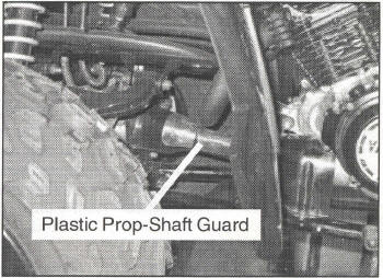
1. Remove the front plastic prop-shaft guard, Figure 1. There are three bolts securing the guard into place, two on the differential and one near the engine. Set guard and hardware aside for later use.
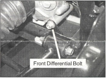
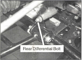
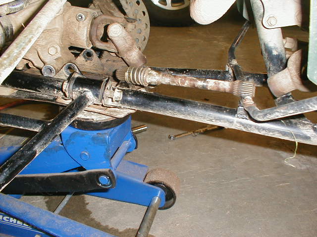
2. Remove the front and rear bolts that hold the differential into position. The front bolt location is shown in Figure 2 and the rear bolt location in shown in Figure 3.
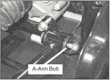
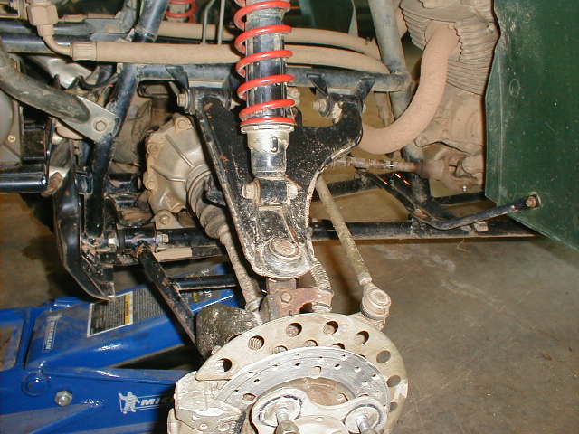
3. It maybe necessary to loosen the A-arm bolts to remove the differential bolts. It is not necessary to remove the bolts. Just loosen and slide bolt enough to remove the differential bolts. Figure 4 shows the front right A -arm bolt loosened and moved to allow the front differential bolt to be removed.
|
|
|
|
|
|
|
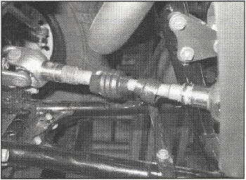
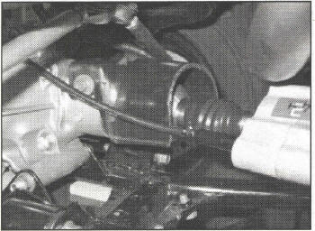
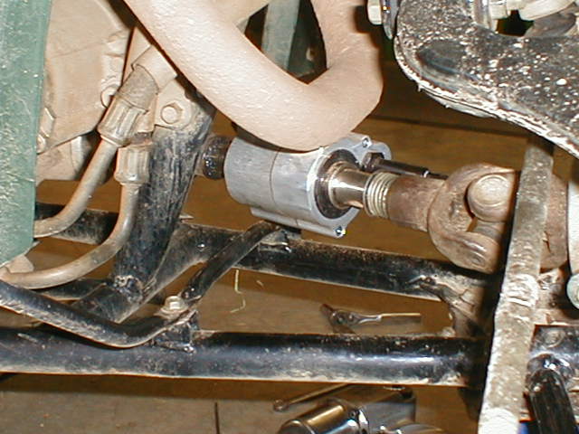
I. FRONT SHAFT REMOVAL continued.... 4. CAREFULLY slide the protective boots to expose the U-joint connection and retaining rings on each end of the shaft Figure 5. The boots will be re-used on the new 424 Select unit. 5. Pull the differential forward, towards the front of the ATV, to remove the prop- shaft from the U- joints. Remove the shaft from the ATV. Note: Be careful not to loose the spring and thrust washer on the differential side of the prop-shaft. |
|
|
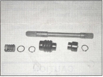
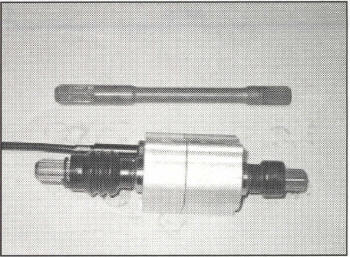
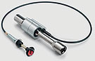
II. SELECT INSTALLATION 1. Remove both protective boots, retaining rings, thrust washer and spring from removed prop-shaft, Figure 6. All components will be reused in the 424 Select application. ~~ ~~ ".-. 2. Place the shorter protective boot and one retaining ring onto the input side ofthe 424 Select unit, the shaft opposite side of the cable. The protective boot must be placed on first with the retaining ring to follow, Figure 7. 3. Place the longer protective boot onto the output shaft, the side the cable is coming out of. Place the retaining ring onto the shaft followed by the thrust washer and spring, Figure 7.
CAUTION
|
|
|
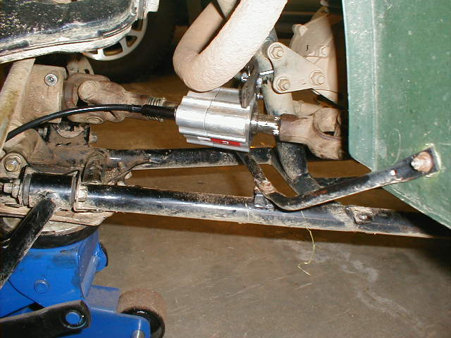
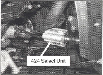
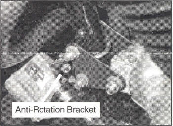
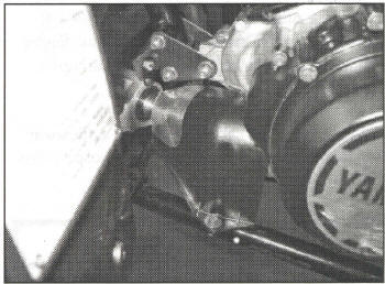
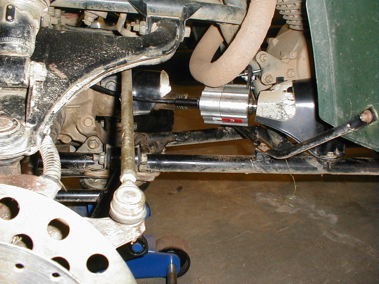
4. Install the 424 Select unit onto the ATV in the same location as the removed prop-shaft, Figure 8. Align the 424 Select unit into the engine side V-joint first. Next, pull the front differential forward so that there is enough room to slide the unit onto position. It maybe necessary to rotate the differential slightly until the splines line up . 5. Reinstall the front differential mounting bolts and tighten all fasteners to the recommended torque settings located in your owners manual. 6. Using a 5/64" Allen wrench, attach the anti- rotation bracket to the 424 Select using the 8-32 screw and lock washer, Figure 9. Do not tighten at this point. Attach the anti-rotation strap to this bracket using the 1/4-20 bolt, fender washer and lock nut. Attach anti-rotation strap to frame using W' - 20 V -bolt, washers and lock nut provided in kit Figure 9 and Figure 10. 7. At this point the anti-rotation bracket and all other mounting hardware can be tightened.
CAUTION
|
|

|
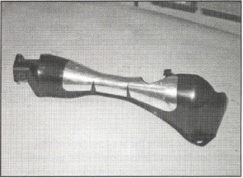
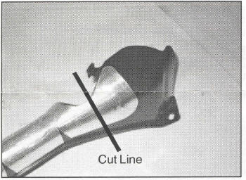
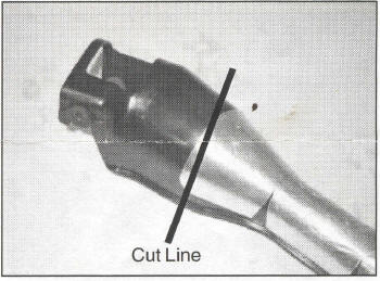
8. It is recommended to modify the plastic prop- shaft guard and reinstall onto ATV to protect the U- joints. Refer to the following Figures for the recommended cutting location. 9. Reinstall the V-joint guards and secure with the original hardware used to secure the plastic prop- shaft guard. |
|
|
|
|
|
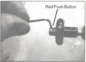
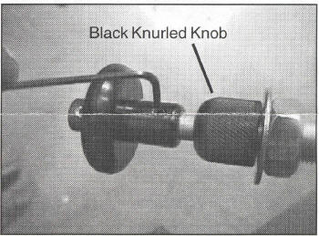
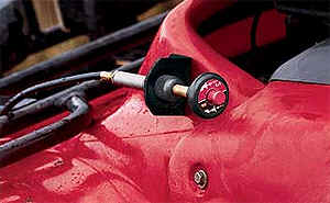
III. CONTROL CABLE ROUTING 1. To route and install cable it is necessary to disassemble handle. Remove red push button by loosening setscrew, Figure 16. Depress button while loosening screw and release slowly, remove spring, Figure 17. 2. Loosen setscrew in black handle and remove. Remove black knurled knob, washer and mounting nut, Figure 18. 3. Route cable using the least number of and largest bends possible to allow for the smoothest operation of cable. The initial routing should be above the differential and below the steering control arms. |
|
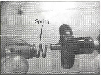
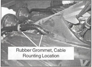
Figure 17 Red Push Button and Spring 4. Slide the rubber grommet, located on the left front side of the ATV, away from the plastic fender so that the cable can be routed through this area, Figure 19. 5. If necessary, use cable ties to keep cable away from moving parts. If used, keep ties loose to allow free operation of cable.
CAUTION |
|
|
III. CONTROL CABLE ROUTING continued....
WARNING |
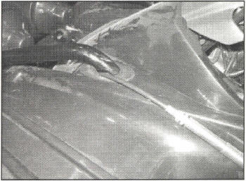
Figure 20 Cable Routing 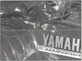
Figure 21 Cable Bracket Location |
|
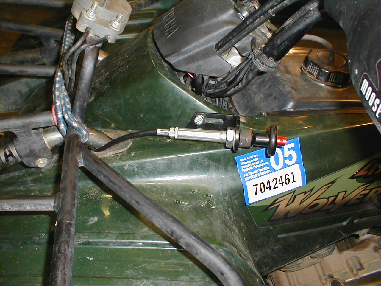
CABLE ADJUSTMENT Test for proper operation of the 424 Select unit. The cable should have a smooth pull and should positively lock into the 4X2 mode when pulled. Release the cable and shift into 4X4 be depressing the red push button. If cable assembly feels stiff or will not lock into position, adjust cable assembly in at. th~ adjuster (less thread showing) until proper feel is achieved Figure 22. |
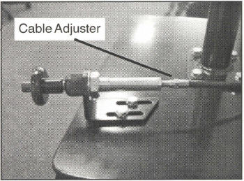
Figure 22 Cable Adjuster |
Totallyamaha is not responsible for any damages that these modifications may cause to your vehicle; any modifications are your responsibility if you choose to do so. We are providing information ONLY. Some of these modifications may VOID your warranty and that is your responsibility to look into. The Totallyamaha users have passed along most of the information found on this site. If you have any questions or concerns about anything on this site talk to your dealer before using any of the information. Totallyamaha will not be liable for any damages or personal injury from any modification performed from this site.
Please let us know if you have anything to add to this page to help out other Yamaha owners. For addition to this page Email webmaster@totallyamaha.com
![]()