 |
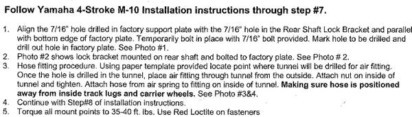
 |

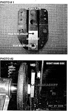
Fast Inc Air Wave Install for Apex
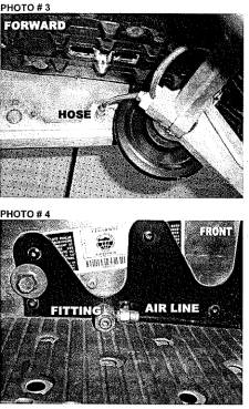
Note:
More Info in the following links
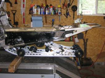
Suspension Removal (Click Link)
Read Suspension Removal link above and remove rear skid. Once the stock suspension is out you would remove the 2 Allen head screws that hold on the exhaust caps. Remove the large Phillips head screws that hold on the rear plastic around tail light. Remove that plastic to gain access to the j-hooks that hold down the seat, remove the 2 nuts on the end of the j-hooks that hold the seat down, unplug the tail light harness that is slightly tucked under the right side tank cover and remove the seat.
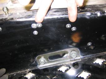
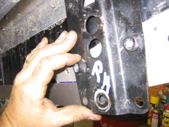
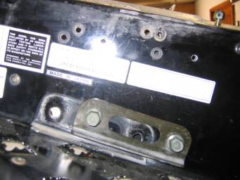
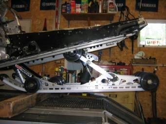
Starting on the inside of the tunnel on the left hand (LH) side located the stock rear suspension mounting plates (black in color). Label the plates LH and RH do be sure they go back on the correct sides of the tunnel. On the outside of the tunnel remove the two lower bolts that hold the plate to the tunnel. Then drill out the rivets that hold the upper portion of the plate to the tunnel. See Photo
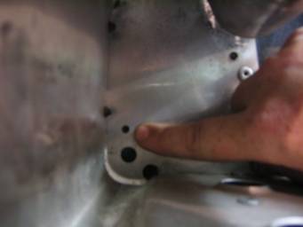
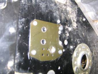
At the front of the sled, on the left hand side, locate the small pilot hole under the foot hold above the holes that would have been used in the older RX style tunnels. See Photo. Drill that pilot hole to 29/64”. This will be the new Air Wave front mounting hole. You can access this area on the front of the tunnel by removing the side panel uppers and lowers.
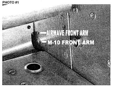
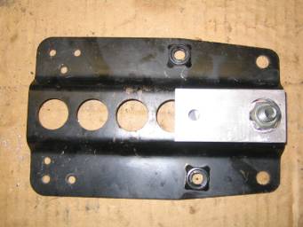
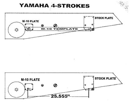
At this point I took the small black tunnels supports provided by Fast and drilled the same 29/64 hole thru one of the many holes that best suited for my installation by putting the plate over the predrilled tunnel hole, I could then see what tunnel rivets would interfere with the plates and notched or drilled additional access to allow the plate to sit flat in the inside of the tunnel. After front supplied support plates have been modified, bolt the plate in place with provided front mount bolt and nut. Be sure the top of front support plate is parallel to top of tunnel. Mark the four 3/16” holes in the four corners of the plate and drill through tunnel. Rivet into place. See drawing #1. Apex RT & Apex GT use different tunnel bracing inside tunnel which may involve trimming the front M-10 plate to fit accordingly.
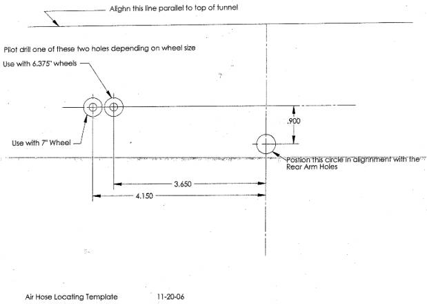
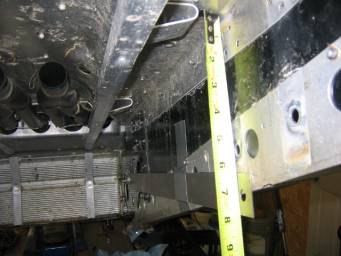
Measure down 7.047” or 179mm from the top of the tunnel to the center of the predrilled hole at the rear of steel tunnel template. Temporarily secure (duct tape) the template to the inside of the tunnel.
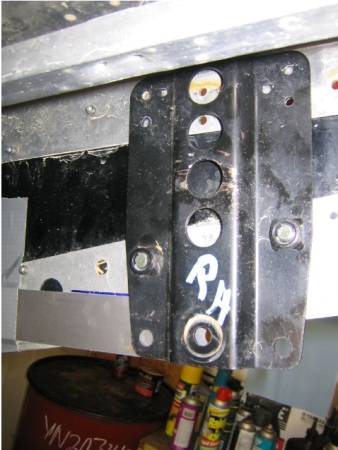
Place the LH stock plate, which was removed earlier, between tunnel and template and line up the rear stock hole with the hole in the M10 template. Make sure rear factory plate is parallel with top of tunnel. Mark holes in the factory plate. Remove M-10 template. Drill holes marked in tunnel.
Perform the same steps/procedures for Right Hand Side [RH] of tunnel and remove the rear mounting bracket for installation of the suspension.
Note: The LH and RH stock plates will be attached to the rear arm of the M-10 before installing into tunnel*
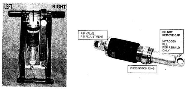
Using nuts and bolts provided attach shocks to M-10 arms and torque to 35lbs. Attach lower end of limiter strap in hole specified on M-10 setup card.
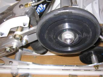
Install shaft and spacers on front M-10 arm. Install shaft, wheels, and spacers on rear M-10 arm. (Be sure to check note on wheel). This is a good time to grease the [4] fittings with low temp grease.
The LH and RH stock plates will be attached to the rear M-10 arms with the 7/16” bolts provided. The rear arm of M-10 will use the factory hole drilled in the factor plates. With the bolts partially installed, but not tight, turn the suspension upside down. With the suspension upside down, lay the flat edge of both LH and RH stock plates against garage floor to keep them parallel. Hold down on plates to keep them parallel to floor and each other, torque each bolt to 35 lbs. [Be sure to use lock washers ONLY on those bolts.]
Place M-10 inside of track.
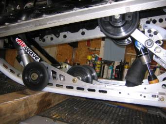
Install front M-10 arm into the new locating holes drilled in tunnel. Using the 7/16” Allen bolts, lock washers, and flat washers provided torque to 35 lbs. The turned out upper edges of the stock front brackets need to ground flat for property fitment of front M-10 shaft. See photo #6 (BE SURE FUEL VALVE IS OFF).
Lift up the rear of the M-10 and align the holes in the plates with the new locating holes drilled earlier. Install the original factory bolts to secure plates into tunnel. Install the 10-23 button head bolts and nuts provided into the rivet holes drilled out earlier.
Install seat.
>
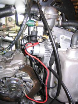
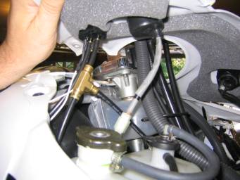
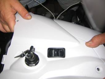
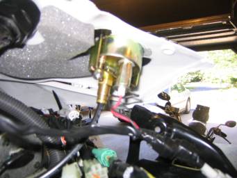
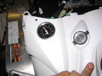
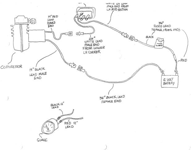
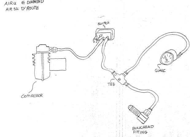
The following pics are the actual areas we selected for the compressor mount (near the oil tank), the switch and gauge mounted into the access panel between the handle bars and the gauge pod.