Apex Stage 1 Super charger Installation
Instructions
Read and understand these instructions
Thoroughly BEFORE beginning installation.
-The Super charger is shipped with oil in the system; pre-primed and sealed. Don’t remove hose ends seals until directed to in the instructions.
-Bolt and screw sizes called out are the thread size, not the wrench or socket size.
-Left Hand (LH) and Right Hand (RH) references always assume you are sitting on the sled.
-This installation
requires a high quality Inch-Pounds torque wrench, 1/8” & 4 mm hex key
sockets.
Remove Stock Parts:
- Air Box – not used
- Nose Cone (6 Phillips Head flange screws) – reused
- Battery – not used
- Unhook started Relay from Batter Holder – leave Relay wired in sled.
- Unbolt ECU (Electronic Control Module) mount from Battery Holder
- Remove Battery Holder – not reused (RETAIN Rubber Strap, this is reused)
- Unplug and remove ECU and Baro Sensor from sled.
- Remove Voltage Regulator & Bracket – Leave Regulator attached to its Bracket to reuse later.
- Unplug and remove oil dip stick and O-ring - reused
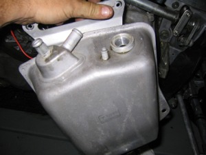
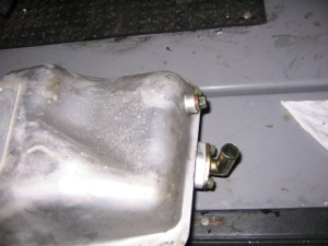
- Drain oil, remove all lines from tank and remove Dry Sump oil Tank - Tank not reused
- Remove bottom oil pickup fitting from OEM oil tank and discard O-ring
- Remove Right Hand side upper and lower pod – reused
PTO Install
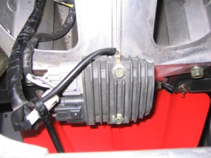
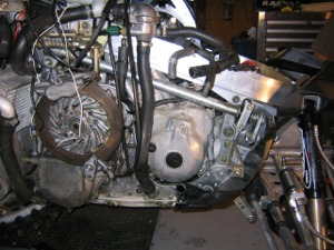
- Pull remove and discard long small black air box drain hose and clamp. On the right side of the motor.
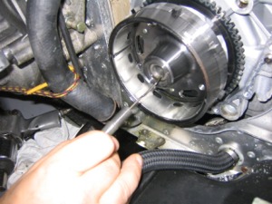
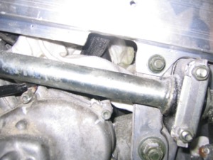
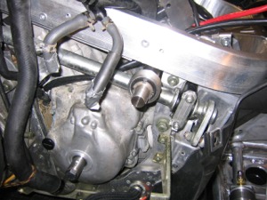
- Push/move thermostat bypass hose to rear and secure with rope, bungee or tie down. See Figure 3.
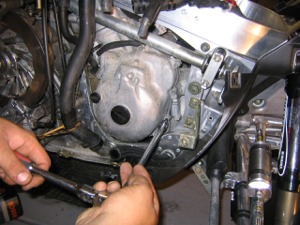
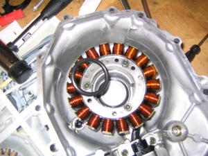
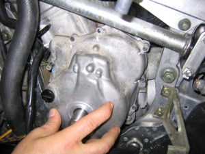
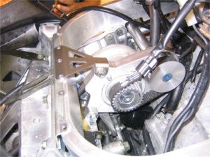
- Remove 11 Allen head bolts paying close attention to the 3 different sizes and the location of each size. (1 long, 5 medium and 5 short bolts as well as the wire bracket on upper bolts). Note: Short bolts are around the bottom.
- Carefully pull out on the cover – use caution with the gasket. May require a pick or similar tool if you wish to try and save the gasket as this gasket will not be included in the MPI kit. We found that the gasket is fairly inexpensive and it would be much easier to have one on had and replace during reinstallation of cover.
Note: Additional oil will drain
Note: The larger inner magnet will pull against you trying to keep the cover in place.
Note: Starter drive gear and pain may fall out – small gear faces in; large gear faces out.
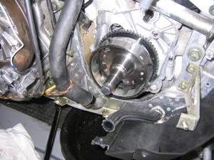
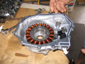
- Remove and discard stock crank bolts and washer with 19mm socket using ½ impact wrench. Standard Right Hand thread. See Figure 4.
Note: There is a bent wire that goes inside the crank bolt. Remove and save wire to go into the new crank bolt!!
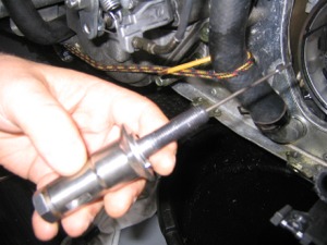
- A.
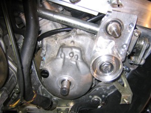
Install new longer bolt, smaller washer, PTO extension shaft and OEM wire
from above inside the new bolt. See Figure 5. Insure that the
pilot shaft on the PTO extension shaft goes inside the flywheel bore and the dowel pin in the new PTO
extension lines up with the keyway slot in the flywheel.
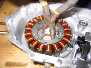
B. Lock primary clutch with long shaft (like a pry bar or primary holder) See Figure 6.
C. Torque new bolts to 94 ft-lbs.
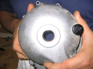
- Remove and discard larger plastic plug in side cover.
- Clean inside surface around threads and the threads (must use solvent, such as brake cleaner or the Loctite will not work) Note: avoid solvent contact with magneto coils and wires
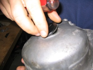
- Install the loose thinner diameter black O-ring (there is a 2nd small dia o-ring sued in the fuel return block but its slightly larger) inside the case cover 1st around the thread boss on the inside and then install the thicker diameter O-ring on the top of the thinner O-ring.
- Apply blue Loctite to the seal housing and install to the inside side cover from the inside. Tighten seal housing with a large rigid pair of snap ring pliers or needle nose pliers to about 20 ft-lbs. See Figure 8.
- Clean and inspect OEM side cover gasket for tears and rips. Replace if damaged. Clean side cover and crank gasket surfaces of all residues from gaskets to assure good contact of gasket and sufficient sealing.
- If you are reusing old gasket then apply a small amount of 3M semi –drying 1103 or semi-drying Yamabond 1215 (silicone will work in a pinch) to only 3 locations. 1 & 2 where the crankcase halves meet and 3 around rubber wire gasket at the top rear of the cover. I believe with the new gasket and a clean surface this would not have to be done.
- VERY IMPORTANT!!! Lube new PTO
seal and PTO shaft with a light coating of engine oil.
- Re
verify that the starter gear is correctly installed with the larger gear
facing out. See Figure 4 and Figure5
- Install
gasket onto crank case first. Insure that the 2 hollow dowels that locate
the cover are in place on either the cover of the crankcase.
- BE
VERY CAREFUL TO NOT DAMAGE THE PTO SEAL WITH THE PTO SHAFT. Seal can “roll over” during
installation and permanently damage seal. DO NOT PUSH ON COVER.
Note: The magnet will try and pull the cover from your hands – seal/shaft alignment is critical.
Note: Don’t pinch stator wires (or fingers) between cover and case.
Note: There will be noticeable friction on the cover if the seal has rolled over. Once cover is in place try pulling cover in and out 1/8” to ¼” a couple times. Free movement against and with the magnetic force is good.
- Reinstall 11 OEM Allen head bolts noting the location and size. (Long Medium and short bolts). Also note the position of the clip. Torque to 9 ft-lbs. See Figure 9.

Blower Drive
- Prepare to cut lip on the right side of the Delta Box. Plug all oil, water, fuel and breather lines & barbs with rags or tape. Thoroughly plug and tape the throttle body intakes. Move wires on the inside of the delta box out of the way.
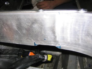
- Using a body saw or other suitable cutting tool to remove the lower lip of the Delta Box as shown in Figure 10. 1 ¾” inches back from end of the casting to the Delta box joint. Even with the bottom of the “box” portion of the Delta box. What may also help you do the trimming is drill ¼ holes into the corners of what needs to be trimmed, score with cut off wheel between holes and break off remaining. Use a file to clean up remaining metal.
- Using the same tools and method as list in step 19. Trim the lower lip on the front of the Delta box. See Figure 11. Use a square to locate the center of the Delta box. Cut a clearance radius or drill out the corners as stated in step 19. The highest point of the radius will be the underside of the Delta Box frame approximately ¼” up from the bottom of the Delta box lip. (You will be removing this lip). Beginning of the clearance arc is 2” from he Delta box centerline and the end is 4” from the center. See figure 12.
- Vacuum as many chips as possible. Remember the air flow comes from under the hood. All residue must be removed. Blow remaining chips thoroughly using compressed air. It should take 2 to 3 times longer to clean than the cutting and measuring did.
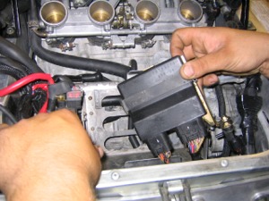
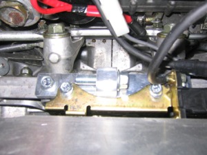
- Put starter relay on the new relay mount bracket. The fuse side of the relay pushes on the bracket first. The large wires are on the outside of the bracket (further away from the Delta box).
- Slip the bracket behind the plastic flat OEM wiring cover and bolt the new relay bracket assembly to the Delta box as shown on Figure 13 using an OEM 8mm flange bolt. Rotate the bottom of the relay assembly towards the back of the sled as far as possible.
Blower Install
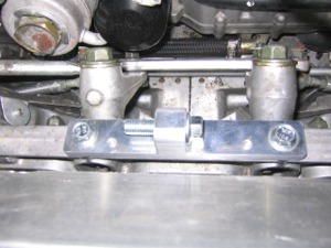
- Install the lower blower frame bracket to the steering rack. This alum bracket has a long leg and a short leg; the long leg goes to the left hand side of the sled. Secure both the lower blower frame bracket screws to the steering rack using the 2 new M8 x 20mm flange head bolts provided. See Figure 14. Use blue Loctite and torque to 25 ft-lbs.
- Slide
a new M10 x 40 mm flange head bolt through the ear. This bolt will thread
into the main blower bracket later. The bolt must be placed through the
ear now. This bolt can be seen in
Figure 16.
- Elongate the 2 holes in the gold OEM ECU bracket and remove the ear on the back of the bracket. This will allow you to align the bracket with the holes in the blower lower frame bracket. The elongation extends towards the cut edge of the gold bracket (not the bent edge). The slot will be about 3/8” long from edge to edge. A round filed works really well to elongate the holes. See Figure 15.
- Mount on the OEM ECU bracket to the lower blower frame bracket using 2 new M6 x 10mm long flange head bolts along with the flat washers that are included. See Figure 16.
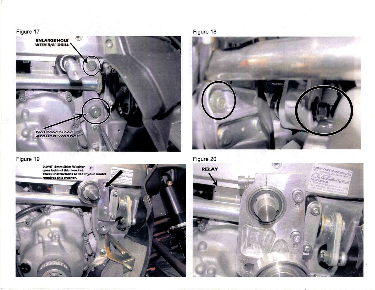
- Remove the front lower mount nut M12 (17mm head). Discard the M12 nut and washer. Remove and discard the upper M8 nut and washer connecting the Delta Box to the front bulkhead. Only the M8 and 12 mm flange head bolts will be reused. See Figure 17&18.
- Enlarge the 8mm top hole as shown in Figure 17 to 3/8”. Drill through both the die cast frame and the Delta box flange.
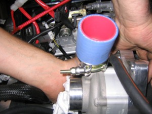
- Install one 3” long piece of 1 ¾” ID silicone hose onto the blower outlet. Slide hose onto the blower as far as possible. Clamp in place using 2” stainless tee clamp. The bolt end of the clamp should be on the bottom and point to the right hand side of the sled.
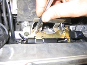
- Straighten locking tab on the front side steering column near the side relief you cut into the Delta box. Remove 2 M8 nuts, locking plate and the ticker plate just behind the locking plate. Remove the outer black steering column bushing. The inner bushing can stay in place as well as the studs.
- Loosen, do not remove, the 3 nuts that hold the rear end of the side steering column. You will have to remove the 3 Hair pins before you loosen the nuts.
- Slide blower assembly into place. The short oil line runs on the left hand side of the blue silicone hose and the long oil hose/filter runs behind and under the blower and runs forward on the right hand side of the blue silicone hose. The shaft and bearing pass between the Delta box and the steering column. You will have to pull the column out and down so that the bearing cartridge will clear. You can also turn the steering and that may help may some clearance.
- Install the blower on the right hand side of the ear on the lower blower frame bracket. See Figure 16. Using the new M10X40 mm flange head bolt you slid through the ear earlier, thread it into the main blower bracket. ONLY FINGER TIGHT FOR NOW, we want the unit to rotate about the bolt, but not wiggle sideways.
- Reassemble both ends of the side steering column. Don’t forget to reinstall the “4 Hair Pins” in the upper rear end of the column and bend over the 2 locking tabs on the lower front locking retainer.
Note: When we did this install we found that we did not have to loosen the upper 3 bolts, just the lower steering mount. Once we turn the steering to pushed the column out enough that we could get the blower in place.
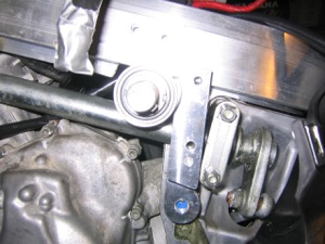
- CAUTION: INCORRECTLY FOLLOWING THESE STEPS WILL CAUSE BEARING FAILURE!! Apply blue Loctite to both the M8 and M12 bolts and screw them into the New Idler to the frame bracket. You will need to install a special M8 thin (.045”) fender washer between the bracket and the bulkhead. Thread both the OEM m8 and M12 bolts into the new bracket. Snug the M12 bolt from the inside and rotate the top of the bracket towards the rear of the sled. DO NOT USE ANT OEM WASHERS BETWEEN THE FRAME AND THE MOUNT (only the 8mm .045: washer). Both the 8mm and the 12 mm bolts should be finger tight (so the socket can move just a little). See Figure19.
- Remove the top M8 socket head screw and washer from the idler mount. You may need to open the slot in the bracket slightly so that the bearing cartridge will slide into the bracket. Be careful not to mar or scratch your pretty bracket. Leave this bracket pried open until later directed to remove the jamming device and install the bolt and washer. Slide the idler/bearing bracket over the blower bearing cartridge end. There are 2 dowel pins in the outer idler bracket that will mate into the side frame mounting bracket. Tap the outer bracket on evenly. Apply blue Loctite to the 2 new M8x25mm socket head bolts and install them connecting the 2 new brackets together. Torque to 20 ft-lbs. See Figure 20:
A. Remove 3 rivets on the top of the Delta box. See Figure 22. Install new upper blower stainless steel frame mount. Using new M10X40 flange bolt and flange nut; do not tighten. See Figure 23. Install 1st of 3 rivets in existing hole. Use the bracket as a template and drill 2 new holes into the Delta box with a 3/16” drill. Install 2 more rivets.
B. Blower Drive Alignment: Fully tighten both the M8 and M12 bolts. Torque M8 to 20 ft-lbs and the M12 to 50 ft-lbs. Refer back to Figure 17 & 18.
C. Fully tighten the 10mm lower frame mount bolt. Refer back to Figure16. Tighten lower M10 bolt and torque to 35 ft-lbs.
D. Fully tighten the top M10 adjuster bolts and nut. Torque to 35 ft-lbs. See Figure23.
E. Remove the jamming device or release the idler center bolt and reinstall the top M8 socket head screw and washer you removed earlier. Apply blue Loctite to the M8x30mm socket head bolt. Torque 15 ft-lbs. Revisit Figure 20.
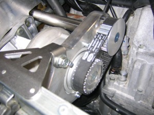
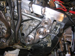
- Install drive sprocket, driven sprocket and belt
A. Clean Shaft, bore of bushing, outside of bushings and hub and bores on sprockets with brake cleaner. File and burrs.
B. Verify that the Woodruff key is installed into the end of the jackshaft. You will have to tap this into the shaft, use a plastic mallet or dead blow hammer. BE CAREFUL TO NOT mar or damage the key. The top of the key should be flat or parallel to the shaft. You may tap on one end of the key to align the key as required.
C. Install the Woodruff key into the PTO stub shaft as detailed above. You may have to tap this into the shaft, use a plastic mallet or dead blow hammer. BE CAREFUL TO NOT mar or damage the key.
D. The outside (facing you) on both the sprocket and the bushing will have 3 semi-circular holes. DO NOT lubricate the sprocket or the bushings. Lightly coat the set screws with a thin layer of anti-seize.
E. Put the bushings with the larger 7/8” hole into the drive sprocket (26T) from the outside. Start the 2 set screws into the holes that are 180 degrees across from each other. About 5-6 turns on the set screws so that the bushing still moves up and down just a little bit. Repeat process with the driven sprocket (22T) and the smaller3/4” bushing. NOTE: To remove sprockets from shaft, remove 2 set screws, and install 1 set screw into the hole between the 2 holes that are 180 deg opposed. Tighten the single set screw and the assembly will pop loose. See Figure 21.
F. Loosen the jamb nut on the idler adjuster bolts and slide idler back as far as possible.
G. Install the 2 sprockets/bushings and belt together in one operation.
H. CAUTION: USE INCH POUNDS TORQUE WRENCH. WRONG TORQUE WILL CAUSE DAMAGE. Push the driven sprocket (upper) against the bearing locknut on the jackshaft. Alternately torque the setscrews to 54 in-lbs. Repeat the process until neither set screw will move. Keep force pushing in on the sprocket during initial tightening to avoid a gap between the bearing nut and sprocket.
I. Align the outside edge of the 2 sprocket faces. See Figure 24.
J. Using the same torque sequence, tighten the drive sprocket into place. Noting alignment. Note: as you tighten the set screws the sprocket will move out. You must account for movement so that the faces of the sprockets are aligned after both sprockets have been torqued into place. NOTE: RECHECK SET SCREW TORQUE AND BELT TENSION AFTER FIRST RIDE!!. Verify that the drive lower sprocket does NOT rub on the motor side cover (both sprockets cane be moved out slightly if necessary to prevent rubbing..
- Belt adjustment. Snug M12 main tensioner bolt/nut so that the tensioner barely slides. Adjust tension with the M8 adjuster bolt. The long side (upper) of the bolt should NOT be able to touch the other side of the belt as it runs over the idler pulley. It should require about 4 lbs of force to make the 2 belt inside move ½ the distance from touching. (Using one finger and pushing firmly, you should not be able to make the belts insides touch). Once the desired tension is set with the M8 adjuster bolt, tighten main M12 nut and bolt to help lock the tensioner. Push idler against adjuster bolt as you tighten. The idler will tend to walk out, making the belt tighter. Recheck belt tension after the M12 bolt had been titghtened. Tighten M8 adjuster jam nut. NOTE: RECHECK BELT TENSION AFTER FIRST RIDE!! Then recheck every 100 to 200 miles.
OILING SYSTEMS
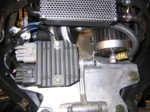
- Install the voltage regulator. See Figure 32 & Figure 33. The regulator still uses the OEM bracket. It is simply shifted to the right hand side of the bulkhead instead of straddling it as installed from factory. Use the new M8 x 110 (or 120)mm bolt and 1.9” long spacer. The lower blower tank bracket also mounts on this bolt. Use the OEM nut. (Note: the mounting tab on the lower oil tank bracket points down, while the upper one points out sideways.) From left to right assemble as follows: bolt, blower bracket, bulkhead, regulator left hand tab, spacer, regulator, right hand tab and nut. The regulator and the tank bracket should point straight up.
- Remove and discard the stock M6 flange head bolt that hold the regulator to the OEM bracket. Replace it with a new M6 x 35mm (or 40 mm) fully threaded flange bolt.
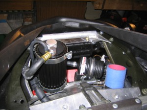
- Mount the blower oil filter using the rubber lined Adel Clamp provided. The filter mounts on the backside of the top regulator bolt you just replaced. Use 2 large M6 washers. Slip the 1st washer on the bolt, then the 2 tabs of the Adel clamp, then the 2nd washer and finally a new M6 flange nut. Tighten the nut. Once tight carefully twist the filter (bending the tabs of the Adel clamps). Rotate the left side of the filter towards the front so that it sits at a 45 deg angle. See Figure 32.
- Install the upper blower tank mounting bracket by removing the 2nd M6 flange bolt back from the front on the left hand side of the sled on the hood hinge mounting bracket. See Figure 30. Put OEM bolt through the further out of the 2 holes in the tank bracket. Reinstall the bolt and bracket. As you tighten the bolt keep the clamp rotated forward.
- THIS STEP AS BEEN REMOVED due to updates to kit.
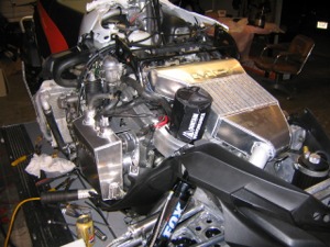
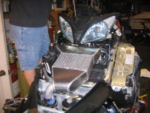
- Remove and discard the OEM front 2-6mm flange head bolts and nuts that hold the front OEM aluminum hood brackets to the side frame supports. Drill through the 2 holes with a 11/32” drill. you are drilling through both the front OEM aluminum hood brackets and the steel side frame supports. (This is only need for a RX1 install Apex install no drilling req’d) The cooler bracket is threaded. Install the supercharger oil cooler under the hood hinge bracket and the OEM alum bracket. (RX-1 does not use the washers due to different spacing requirements.) See Figure 29.
- Connect the oil line to the bottom of the tank that comes with the filter. REMOVE AND DISCARD THE RUBBER SHIPPING PLUGS. QUICKLY CONNECT THE LINE TO THE BOTTOM OF THE TANK. Make sure there is a new copper washer on each side of the banjo fitting. Align filter so that the line is least likely to rub on the fins of the oil cooler. Tighten banjo bolts to 15 ft-lbs.
- Install the top oil line coming from the oil cooler using the same procedure. Remember 15 ft=lbs only on the bolt.
- THIS STEP AS BEEN REMOVED due to updates to kit.
- THIS STEP AS BEEN REMOVED due to updates to kit.
- Secure the blower vent line to the side of the tank using 2 11 inch zip ties. The line points down. Insure that this hose does not kink.
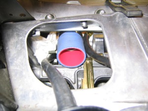
- Install the CAC tube to the blower outlet. Use a 2” tee clamp. The end of the clamp’s bolt should be on the top pointed to the left. The outlet of the tube should point straight up and the welded and plugged bung should point to the left. Tighten the clamp securely. Do Not Over Tighten tee clamps. See Figure 34.
- Thoroughly flush the new oil tank and ensure there is no residue in the tank.
- Remove the gold OEM outlet nipple/inlet screen from the bottom of the OEM oil tank, if not already done. Reinstall the new oil tank. The OEM oil tank has an O-ring groove in the tank. The gold elbow doesn’t have a groove. Discard the OEM O-ring and use the supplied gasket.
- Install new tank onto new lower mount and the 2 OEM top nut inserts in the delta box. You will have to bend the lower mount forward about 1 inch. You may also have to push the top mount down slightly to start the OEM M6 flange head bolts into the delta box nut inserts.
- Clamp the pick up house at the bottom of the tank in place. The clamp should be on the top. See Figure36.
- Route the OEM hoses to the top of the new oil tank as shown in Figure 35. Do not shorten/cut any of the OEM hoses. Adjust all the OEM hose around the “tee” to remove any kinds of wrinkles.
- Watch for signs of wear between the back of the tank and bolt heads in the blower drive system.
- Install the OEM dipstick and O-ring into the new tank. The OEM tank held 2 ¾ quarts to the full line on the dip stick. (Note: Always check oil level with dip stick unscrewed.) The new oil tank holds 2 ½ quarts to the full line. You may run a ¼ quart over full, but it’s not necessary.
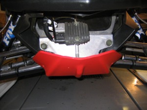
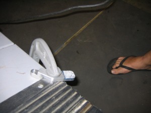
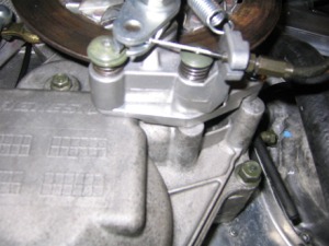
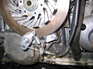
- Install parking brake offset block. See Figures 37 & 38. Remove the parking brake caliper from the chain case (2 M6 socket head bolts)
A. On models without magnesium chain case, bolt the offset bracket onto the forward most post on the chain case using the new M6 x 30 flange head bolt. The large hole on the bracket goes over the 2nd (rearward) chain case post. Bolt the caliper on the new block. Route the cable over the thermostat housing and zip tie hydraulic brake line. Note: If you have reverse you will have to remove some of the bracket and mount bolt threads to allow clearance with the reverse chain case. See pic.
B. On models with the magnesium chain case, you will reuse both OEM round spacers. Use a new M6 x 35 flange head bolt instead of the 30 mm. Also drill out the threaded hole in the new brake relocation block. Use the new M6 flange nut (with blue loc-tite) on the back.
- Install new breather hose on the cast aluminum nipple on the front left side of the motor using a ½” wide worm clamp. See Figures 39 & 40. Route the hose up the left side of the motor below the left most throttle body. Route the hose behind the throttle body heater hose across, up the left side of r the throttle bodies and across the top towards the right hand side. Zip tie into place. Insure that the worm clamp does not rub on anything.
- Zip tie the main dark black oil return hose behind the top starter bolt shown in Figure41. This will keep the hoses away from the blower sprocket and belt.
FUEL INJECTION
MODIFICATION
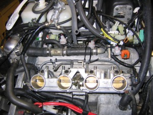
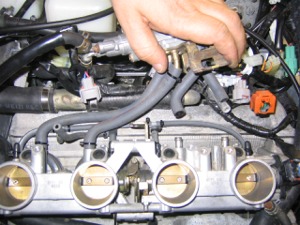
- Remove the 5 gold colored Phillips head screws that secure the IAC (Idle Air Controller) and the fuel injector rail to the throttle bodies. 4 of the screws are in front and 1 in back. See Figures 43 & 44. You do not need to disconnect the water lines from the IAC. Simply move the IAC assembly out of the way. Unplug the injector wires from the factory injectors. Also unplug the MAP sensor wires and vacuum hose. The MAP sensor is between throttle bodies 3 &4 and has a single hose connector. Lift the orange fuel line retaining clip to fully expose the 2 grey buttons on either side of the fuel line connector. Once the orange clip is up, push both grey buttons evenly to release the fuel line. See Figure 43. Next, pull the injector rail evenly off of the throttle bodies. Take care of not to loose any of the seals and O-rings. There is a seal on the bottom of each injector and an O-ring on the top of each injector. The return line can remain connected. Move the assembly out of the way to allow access to the tops of the throttle bodies.
- Remove and discard the 4 OEM rubber vacuum caps. Install 4 new ones with zip ties (they may be cut down in length for appearance. See Figure 44.
- Zip tie all vacuum hoses as shown in Figure 44.
- Reinstall the fuel injector rail and IAC. Make sure to reconnect all wires. Reconnect the vacuum hoses leading to the gold pressure regulator and the MAP sensor with ZIP TIES. Insure all seals and O-rings are in place on the injectors.
- Reinstall the IAC. The 4 larger IAC hoses MUST also be zip tied. Reinstall the fuel supply hose and snap the orange clip back into place. See Figure 43.
FINAL STEPS
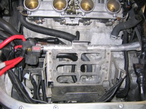
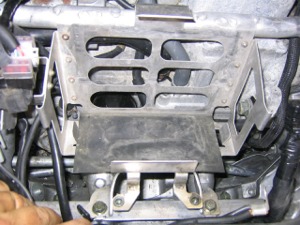
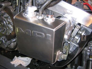
- Install new battery box – route hot and ground wires so that cannot get into the blower drive. Secure cables with ZIP ties. Place the new box in the front of the carbs 1 and 2. The side box bracket is attached to an M8 OEM nut insert on the inside of the left hand side of the delta box with OEM M8 flange bolt. The front box mounting bracket is attached to the top of the delta box using new sheet metal screws provided. The holes are OEM (where 2 rivets were removed on a earlier step(w/3/16” drill)). Rubber air box bumpers have been eliminated from this install. See Figure 45 & Figure 46.
- Install new battery into box with terminals up and towards the blower. The red post is closest to the throttle bodies. Strap the battery into place using the OEM rubber battery strap. See Figure 45.
- Connect
the positive terminal first. By connecting the positive first, if you touch
ground while tightening the positive terminal nothing will short out,
since it will be an open circuit. When disconnecting the battery always
disconnect the ground terminal first. Remember
Ground wire, last on first off!!
- Make one final check for anything that might be able to move and become entangles in or rubbing on the blower drive. Secure out the way with zip ties.
- Install the blue silicone 2 ¼” ID 90 degree elbow onto the blower intake. Secure hose onto blower using a new 2 ¾”-3/8” wide special worm clamps with rounded edges. Use Carb cleaner or brake cleaner to help slip the hose over the blower inlet. Make sure the hose is completely on the blower neck.
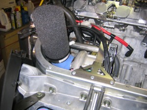
- Install the filter over the end of the blue elbow. (There will be a metal ring inside this elbow). There is a lip inside the black neck of the filter. Push the filter over the blue hose. Push the filter down so that the blue hose bottoms on the lip inside the filter neck. The filter will point straight up when installed correctly. See Figure 47.
- Install 3” piece of 1.75” ID silicone hose on the end of the CAC tube (points up). Slide on so that the end of hose is even with the weld. Clamp in place using 2” Tee Clamp. Do not over tighten.
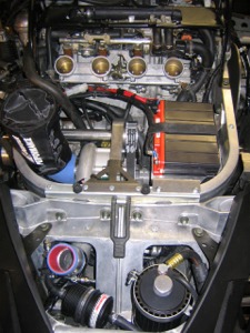
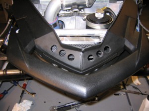
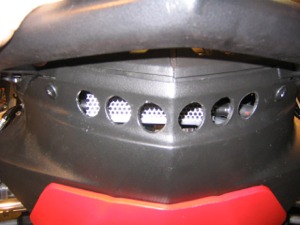
- Drill 6 upper and 6 lower ¾” holes in the front plastic of the sled. These holes are placed at 1” centers. These holes must be drilled to provide proper cooling of the super charger oil. See Figure 48 & 49.
- Reinstall the sleds front plastic nose cone below the hood using the OEM hardware.
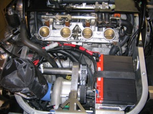
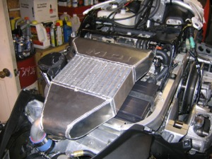
- Install the new aluminum air box/intercooler assembly. The 4 clamps on the Air Box side have been factory installed. No need to move or adjust. Loosen the 4 throttle body side clamps (Note: all the 60mm Oetiker clamps multi positions. Set clamps in the 3rd largest position. Throttle bodies 1 and 2 clamps point up on the left side of the hose. Throttle bodies 3 and 4 clamps point up on the right side of the hose). Push Air Box onto the throttle bodies as far as possible. Make sure the clamps are square on the neck of the throttle bodies, but NOT fully tightened yet. See Figure 49.
- Slide air inlet tube into blue silicone hose. Position a 2” tee clamp so that you can tighten the clamp from the right side of the sled. You may need to reposition the CAC tube for the best alignment. Loosen CAC tube tee clamps and rotate as required to produce a good fit between the air box and the CAC tube. See Figure 50.
- Strap the front of the air box down using the OEM rubber air box strap. See Figure 50.
- Make sure the air box clamps are still square on the throttle bodies. Tighten the clamps ½ way and recheck that the clamps are still square. Now tighten securely.
- Fill the blower oil tank with special “Traction Oil” that was supplied. Fill to Low or Add line and the dipstick. Remember to check both the blower and engine oil with the dipstick unscrewed.
- Recheck
engine dry sump oil level. Remember check engine oil with the sled off.
Check blower oil with sled idling.
Start Up
- Have someone watch the inside the supercharger oil tank with a flashlight. The oil runs down the sides on the inside, so its easiest to observer the oil as it come down the sides and hits the main body of oil.
- Start the sled, If the return oil is not observed within the 1sy 30 seconds, stop the sled.
- Is there is any question about the return oil, remove the top banjo connection from the tank, point the hose into a container and restart the sled. If there is no oil, IMMEDIATELY STOP THE SLED AND CALL YOUR MPI.
- Check the sled for any type of oil leaks, rubbing or interference of any kind.
- THIS STEP AS BEEN REMOVED due to updates to kit.
- Recheck engine oil level.
- Start up and recheck everything.
OPERATION
1. Blower caries a 90 day limited warranty. The warranty expressly excludes overheating! Abnormal use, operation with other that stock ratio and motor operations above 10,500 rpm also voids blower warranty. All blower warranty decisions will be made by blower manufacture, but MPI will assist and interface with factory as required. Warranty also expressly excludes any type of impeller damage. DO NOT RUN UNIT WITHOUT MPI AIR FILTER AND PREFILTER IN PLACE.
2. Your supercharger has an over temperature warning system. It will illuminates the OEM oil level light as well as the warning light on the malfunction display. If the warning light illuminates and you wish to determine if it is low engine oil; stop engine, unplug the engine oil dip stick from the harness and re-start engine. This will simulate a full engine oil tank. If the warning light still illuminates it confirms a blower overheat situation. Note: The warning light takes approximately one minute to set once a hot situation (or low oil) occurs. It also take about 1 minute to reset once a cool situation exists. Stopping and restarting the sled overrides the timer, so that you get an immediate reading.
3. An extra port has been included in the blower oil tank. We recommend you purchase an oil temp guage for the blower. A compact digital unit is available from MPI. DO NOT OPERATE THE BLOWER OVER 180F BLOWER OIL TEMP. We also recommend a water temp guage. MPI offers a 5 function gauge with water, oil voltage, RPM and time. We recommend a water temp less then 200F.
4. A wide band Air Fuel Ratio Meter is highly recommended. A wide band unit will read actual air fuel ratio. 14.7:1 is perfect Stoichiometric ( or theoretical Combustion, which is the ideal combustion process during which fuel is burned completely.) Lean is not quite the killer issue on a 4 stroke (compared to 2 stroke). Air/Fuel numbers as lean as 14.7:1 at partial throttle are not terrible. At WOT you should consider your target to be 12.0:1 to 12.5:1, but note that there was less then a 3 HP range on dyno testing with A/Rs from 12.0:1 to 14.0:1. Idling rich is normal on a RX1 11:1 to 12:1. An inexpensive accurate Digital Recording Air/Fuel Ratio Gauge is available from MPI.
5. Peak HP is achieved at 9800 RPM. Do not operate the blower over 10,000 RPM for to long periods of time (5 to 10 sec max).
6. We recommend 100% race gas at/or above 110 octane. Aviation fuel is NOT the same thing as race gas. AV gas is designed to boil at a lower temp ( high altitude, 15,000ft plus) and is primarily used at partial throttle and low RPMs (2500 RPM, ie Airplane motors.) A minimum mixture of 50/50 is acceptable with pump premium and 110 race gas.
7. Typical Boost numbers of 10 PSI at WOT (this pressure is at an average altitude of 5000ft., lower altitudes will produce slightly higher boost numbers and the opposite for higher altitudes.)
Apex Stage 1 Super charger EFI
Controller Set up
Note: IF YOU ARE RUNNING OUTSIDE 6000 to 9000 ft, you should really have a Wide Band 02 Gauge, since these settings have not been tested yet. Once we have recommended settings an O2 gauge will not be required.
Installation:
- Remove
hood and left hand upper side pod.
- Locate
the grey connector on the top of the delta box left hand side. The
connector is about midway along the delta box. It is a 12 pin connector.
Once side has 10 wires and the other side has 9 wires. Disconnect plug.
Release the OEM grey connector from the clip holding it to the delta box.
- Find a
convenient temporary location
for the controller. You may want to make adjustments as you personalize
the controller for your riding style.
- Connect
the controller into the OEM plugs and snap the controller plug on the
delta box’s mounting clip.
- ULTRA Important: Remove one of the 6mm bolts
that holds the headlight assembly onto the delta box near the grey
connector. You must ground the
black wire running to the control box under the bolt. Reinstall the
6 mm bolt with the wire securely in place.
- Connect
the blue silicone hose to the small nipple on the front of the air
box/intercooler. The nipple is located just above and in-between throttle
bodies 2 and 3. Insure that there
are no kinks in this hose.
- Start
the snowmobile. After a couple of seconds you will see all 8 Green LEDs
scroll across for several seconds.
- Reinstall
the left upper side pod and the hood.
Operation and Tuning:
These setting work well from 6000 to
9000ft.
- With the sled idling you should see #1 LED Green. Number 8 LED may or may not appear Blue at an idle. This #8 Blue Led indicates Boost. Working the throttle should make #8 LED light up Blue. If you never see Blue LED in #8 while riding there is a problem. STOP!!
- There are 8 LEDs and 3 buttons. Each LED can illuminate Red, Yellow, Green or Blue.
- Programming LEDs: LED 2 on equals setting 2, LED 2 and 3 on equals settings 2.5, LED 3 on equals setting 3 and so on (LED 1 fast blinking equals 0.5 and slow blink equals 1). The center button is the Mode button. There are 6 user adjustable modes. Pushing the Mode button will advance you through the modes:
- Mode1: Green– Idle/Cruise Mixture Level – Leave the setting at 0.5 fast blink.
- Mode 2: Yellow – Needle Enrichment- Set at 5. Typically no adjustment is required.
- Mode 3: Red – Main Jet – Set at 7. Can be increased to 8 or dropped. Be Careful, you can adjust to lean.
- Mode 4: Green/Blue – Boost fuel adder. The setting adds additional fuel to the fuel already being supplied in Mode 1,2 or 3. Set at 5.5. This is good adjustment to increase or decrease as you go down in altitude. Try up and down in increments if 1 (4.5 or 6.5)
- Mode 5: Yellow /Blue – Accelerator Pump. Adjust to riding style. Set at 2.5. Very hard acceleration. Set 3 or 3.5. Softer touch on the throttle try 1.5 or 2.
- Mode 6: Red/Blue – Altitude compensation. Set at 2.5. At 6000 feet try 3 to 4, at 10,000ft try 1.5 or 2. Automatic Altitude Comp is coming from MPI.
- The programming mode and the operating mode lights do not necessarily mean the same thing. #8 LED as Blue indicated the presence of Boost.
- Operating LEDs:
- Green (with or without Blue) indicates Idle/Cruise Mode or Pilot Circuit.
- Yellow (with or without Blue) indicates Needle jet enrichment. This circuit is time and only comes on for 1 sec at a time. Typically during medium to hard acceleration.
- Red (with or without Blue indicates Main jet/Full throttle.
- Blue LED in #8 indicates boost. You will always have Green, Yellow or Red LEDs on Starting at #1
- The greater the number Green, Yellow or Red LEDs the harder you are pushing the sled. The number of LEDs actually represents the amount of pulse width the OEM computer is providing.
Notes:
- The
TORS (Throttle Over Ride System) may activate due to fast throttle
closure. This can appear as code 84 (or even 15,16), If this happens let
the sled return to an idle and the code should clear. Stop and restart the
sled if required.
- Even
thought over TORS system by unplugging the single wire with a black
connector and the single wire with a white connector under the plastic
cover holding the key switch and the 12V port and inside the enclosed
rubber wrap completely make this problem go away, we DO NOT recommend
this because of safety concerns. On the TY Sled build install this was
the only way for us to get rid of the TORS error problem. With research
from other installs we found it more of a safety concern to leave it
plugged in. With other Supercharger installs that under testing
conditions the TORS would activate after a high speed run and cause the
sled to go into idle mode. This would cause the track to lock under hard
deceleration from that idle mode.
- Also
shortening the two throttle return springs accessible by removing the air
box/intercooler about ½” eliminates the problem. We don’t recommend this
due to the throttle springs being damaged and allowing the throttle to
stick.
- MPI
is working on programming that will eliminate this issue by adjusting the
response of the throttle position sensor’s input to the factory ECU. This
modification will not require any mechanical alterations, simply
reprogram your controller. MPI will notify you when the upgrade is
available.
- Radical
changes in the controller’s settings can cause serious damage to your
snowmobile. If the sled does not act correctly and anything seems out of
the ordinary compared to your stock unit (other then it hauling some major
ass). STOP and seek advice. Advice is free and motors are expensive.
Possible Setting for See Level (MPI will be testing more setups)
- Green = 1.5 to 2.5 (Start at 1.5)
- Yellow = 6 to 8 (Start at 6)
- Red = 2 to 8 (the higher the Red, lower the Blue/Green)(Start at 3)
- Blue /Green = 4.5 to 7 (the higher the Blue/Green the lower the Red)(Start at 5.5)
- Blue /Yellow = 1 to 2 (Start at 1.5)
- Blue/Red = 8 (leave at 8)
The following are set ups from Allen Ulmer for see level based on Pulley Combinations:
|
|
|
ULMER RACING |
|
|
|
|
|
|
APEX SUPERCHARGED FUEL SETTINGS |
|
|
|
|
|
|
|
|
|
|
|
|
|
|
|
|
|
|
Crank Gear |
22 |
24 |
26 |
26 |
|
|
Supercharger Gear |
26 |
24 |
24 |
22 |
|
|
|
|
|
|
|
|
|
Mode 1 |
1 |
1.5 |
2 |
2.5 |
|
|
Mode 2 |
2.5 |
3 |
3.5 |
4 |
|
|
Mode 3 |
2 |
4 |
5.5 |
6.5 |
|
|
Mode 4 |
4.5 |
5 |
5.5 |
6 |
|
|
Mode 5 |
1 |
1 |
1 |
1 |
|
|
Mode 6 |
8 |
8 |
8 |
8 |
|
