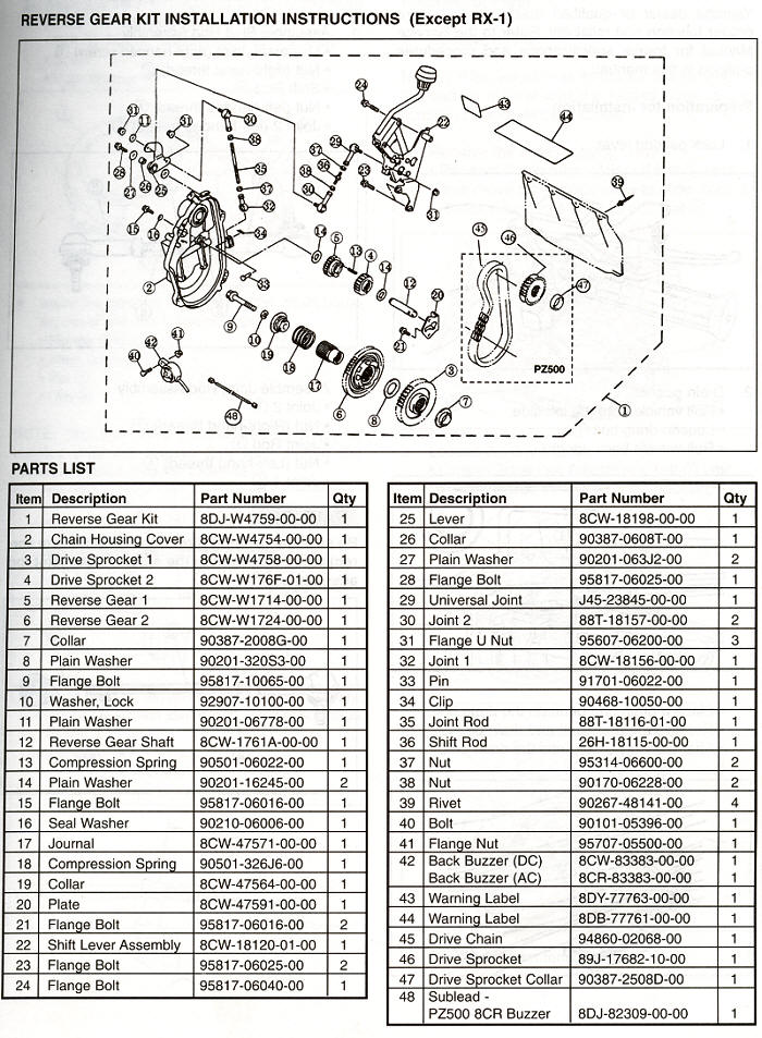
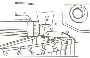
1. Lock parking lever.
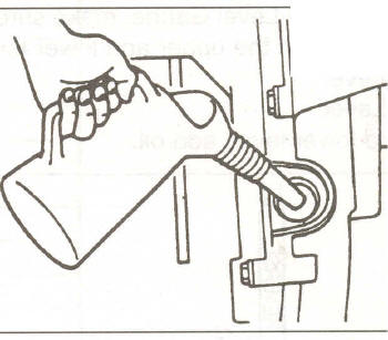
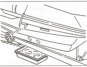
2. Drain gear oil. Roll vehicle onto the left side. Loosen drain bolt CD. Roll vehicle back upright.
Place a drain pan beneath the drain bolt. Remove the drain bolt and drain oil. After draining oil, replace the drain bolt.
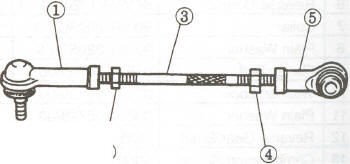
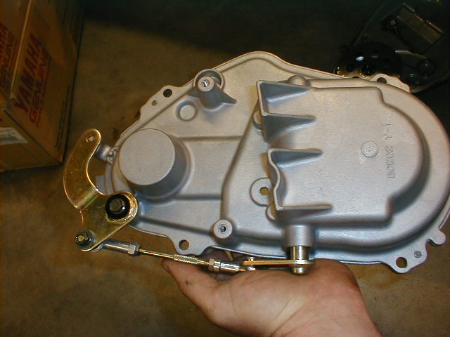
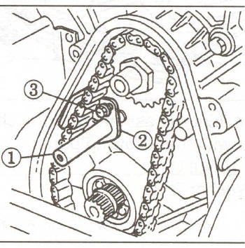
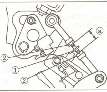
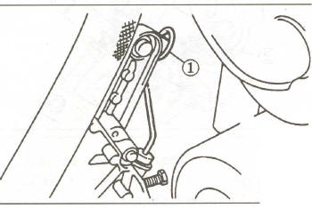
1 . Assemble Shift Rod Assembly
Universal Joint (right-handed screw) (1), Nut (right-hand thread (2), Shift Rod (3), Nut (left-handed thread) (4) Joint 2 (left-handed thread) (5).
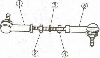
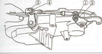
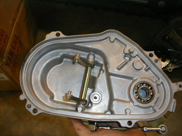
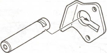
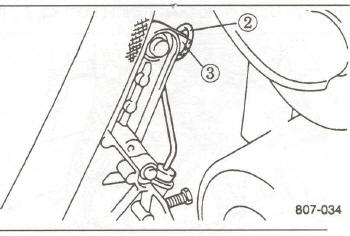
2. Assemble Joint Rod Assembly
Joint 2 (1),
Nut (Right-hand thread) (2), Joint Rod (3), Nut (Left-hand thread) (4), Joint
1 (5)
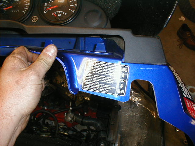
CAUTION
Be sure the rotating direction of threads are cor- rect when assembling the shift rod and joint rod assemblies.