Totallyamaha
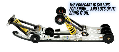
Pro-Action M10-136 w/144 Mountain Performance Tunnel Extension Install
|
|
Before beginning the installation, Totallyamaha recommends that you thoroughly read the installation package provided with your Mountain Performance Tunnel Extension and 136 M-10. Be sure you understand all of the layout procedures described. Take your time with the layout, it is very critical that your new suspension be mounted parallel to the tunnel and perpendicular to the drive shaft. (If any of the information provided below conflicts with the installation package provided by M10 or Mountain Performance, use the their information) Look through the parts that are provided and make sure you are not missing any mounting hardware.
Removal of Seat, Suspension, Chain Case Etc...
Special Note: After speaking with Mac at Mountain Performance and considering a 136" 1 1/4" studded track. Mac recommended a 144 tunnel extension to prevent the studs from reaching the heat exchanger under full suspension compression.
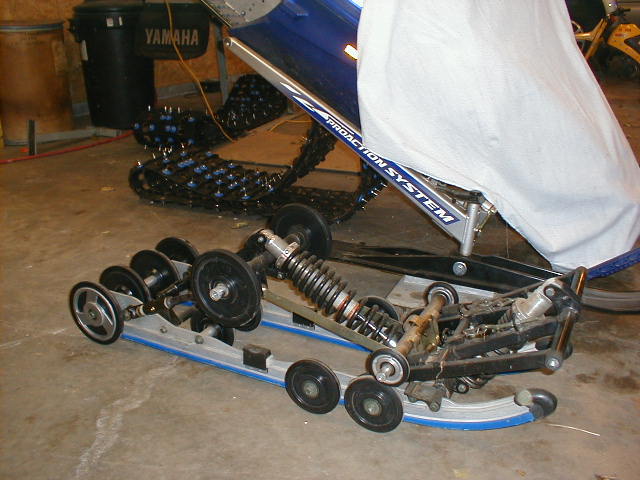
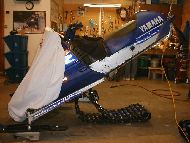
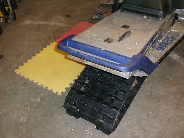
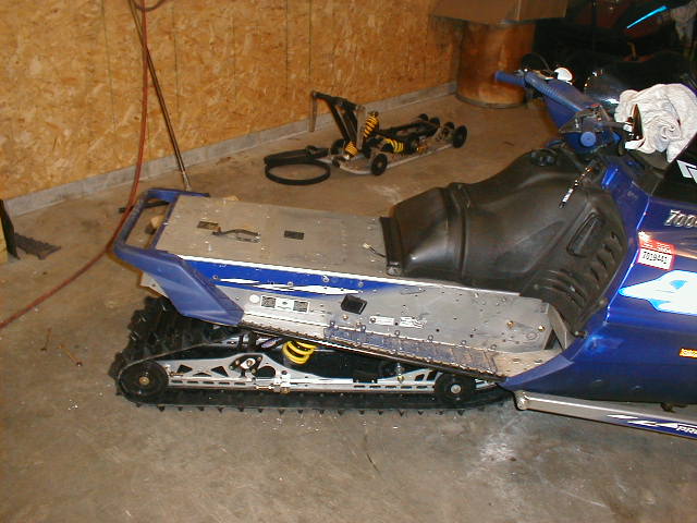
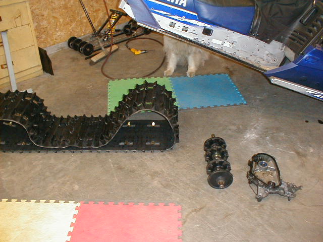
1) Remove your pro-action skid frame by slightly elevate the rear of the sled so the track is about 2" off the ground. Using a 17 mm and 19 mm wrench loosen the rear shaft slightly. Take a 14 mm socket and ratchet and release the track tension. Be sure to count the turns equally off the rear adjusters. Remove all 14 mm bolts 3 per side and carefully lower skid the the floor.
Click Image to Enlarge
Now remove the chain case Drive Axle and Track – click this link for step by step removal Procedure for Replacing your Track found in the tech section in the track area. Refer to the Service Manual for more information.
2) Remove the seat. There are two 8mm (12mm wrench) nuts inside of trunk. Disconnect wire behind gas tank. Set seat aside.
3) The next 2 steps remove the Tunnel & Heat Exchanger Protectors. This is required for 2” track installation. Other kits may retain the guards. PLEASE USE COMMON SENSE AND RETAIN OR REMOVE AS REQUIRED. We skipped the next few steps because we where installing a 1 1/4" track studded with 8 tooth drivers.
4) Remove Front Heat Exchanger Stud Guards if present. BE VERY CAREFUL NOT TO CUT INTO THE HEAT EXCHANGER. Use a cut off wheel (or hacksaw) to separate the bottom of the protector from the heat exchanger fins. Usually by wiggling with a screw driver the top welds will break. If necessary cut the top welds as well.
5) Remove Tunnel Stud Guards if present. The front 3 rivets on each side are under the gas tank. If you wish to not remove the tank, cut the underside of the rivet off. The back rivets are accessible from the tunnel top.
6) Remove the plastic bumper cover. There are three 6mm (10mm head) bolts on each side of the sled (6 bolts total) that hold the cover in place.
7) Remove the rear bumper. There are two 8mm (12mm head) bolts on each side of the sled (4 bolts total) that hold the bumper in place.
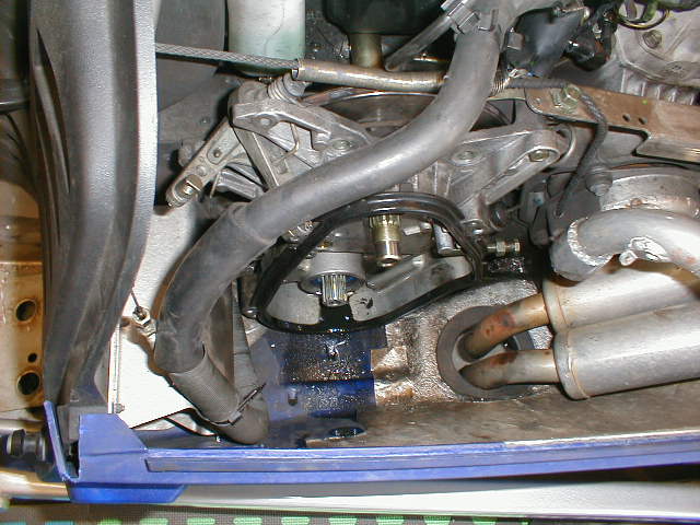
8) Drain the coolant. It is easiest (and cleanest) if a bucket is placed at the rear of the sled under the rubber hose that connects to the rear heat exchanger. Remove the clamp that holds the rubber hose on the rear heat exchanger. Coolant will drain from the exchanger and the hose. Remove the radiator cap under the hood to allow the remaining coolant to drain.
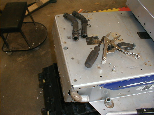
9) Remove and discard the remaining 3 hose claims and the 2 hoses. Additional coolant will drain.
10) Using a 3/16” bit, drill out the 5 rear most rivets located on top of the rear platform. Remove two rivets on each side that hold the tunnel cap to the tunnel. Remove tunnel cap and heat exchanger cross over or heat exchanger.
11) Remove 2 rear bumper reinforcements from the inside of the tunnel (viper only). There are 3 rivets on each gusset.
12) Remove the 2 rear reflectors using a 8mm wrench.
INSTALL TUNNEL EXTENSION & HEAT EXCHANGER
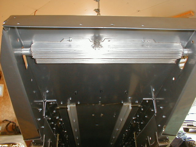
13) Slide the new extension into the tunnel. The extension fits under the OEM tunnel, but a small tab on each side goes above the OEM tunnel.
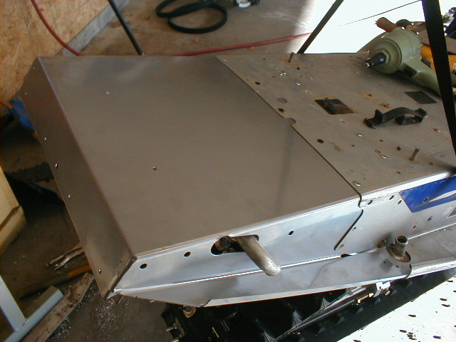
14) Install the top 3 Center Rear rivets first. See Fig 2A. There are pre-existing holds in both the extension and the tunnel.
15) MAKE SURE THE EXTENSION IS TIGHT AGAINST THE TOP OF THE TUNNEL BEFORE INSTALLING THESE RIVETS. Install the next set of 7 rivets as shown in Fig 2A. The circled Rivets will use the OEM tunnel as a template requiring you to drill through the extension. The rivets marked with a square will use the extension as a template and you will drill through the OEM tunnel.
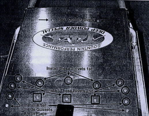
Fig 2A
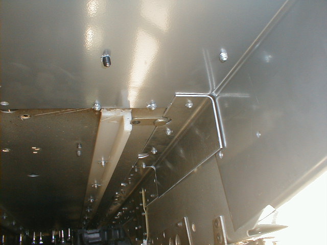
16) Install the inside rear tunnel gussets. The gussets are universal (left and right sides are the same). See Fig 2C. Butt the gussets against the OEM gusset TIGHTLY! Install the 3 top rivets on each side. DO NOT INSTALL ANY SIDE RIVETS AT THIS TIME. There are no template holes. The pattern is not critical and you will not see the rivets, as the seat will cover them. The gusset is designed to overlay the extension. Make sure the gusset is tight against the tunnel/extension as you rivet it into place. ALSO SEE FIG 2B (4 OF THE RIVETS YOU ARE NOW INSTALLING ARE MARKED “INSTALL AFTER INSIDE TUNNEL GUSSETS ARE IN PLACE”).
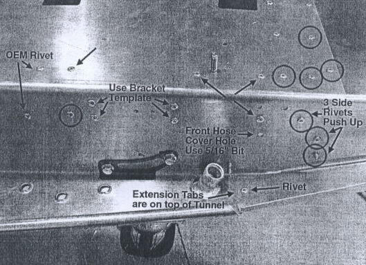
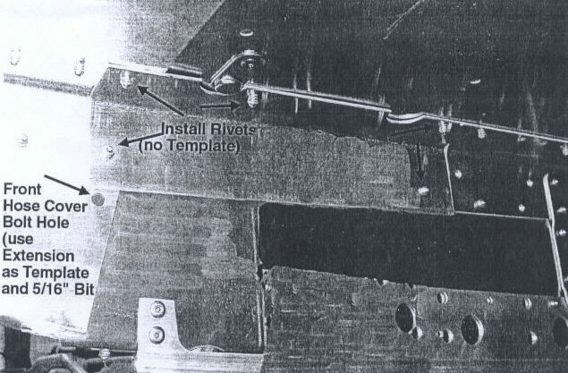
Fig 2B and Fig 2C
17) Install 3 rivets on each side of the tunnel. See Figure 2C “3 SIDE RIVETS PUSH UP.” BE SURE TO PUSH THE EXTENSION INTO THE TOP OF THE TUNNEL. We recommend that you clamp the side of the tunnel as you drill and rivet. The 3 holes are in the tunnel; you will need to drill through the extension. One of the holes may exist in the extension, but may be misaligned; chase the hole with a 3/16” drill before riveting. You may want to install the lower of the 3 rivets from the inside of the tunnel for easier access.
18) Drill and rivet the extension’s tab to the tunnel’s running board. See Fig 2B. 1 rivet on each tab.
19) Using a 5/16” bit and the extension as a template, drill the front hose cover hole through the tunnel. See Fig 2B and 2C.
20) Install the new heat exchanger crossover tube (a larger heat exchanger is available MPI P/N che-0200). Make sure there is clearance between the tube and the hold through the extension. Use a round file, if necessary, on the extension to create clearance. Rivet the tube in place. Insure that the tube is centered in the extension by comparing the space between the tube’s outlet and the side of the extension. If a larger rear heat exchanger is used be sure and drill a clearance hole for the rear cooler bleed hole (1.75”), a pilot hole is provided in the extension. (We installed our new rear heat exchanger instead of the crossover tube.)
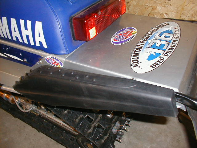
21) Install the mud flap using the 4 larger headed rivets and backup washers provided.
22) Bumper installation will vary for non-Viper installations. Install the rear bumper using the 4 OEM 8mm (12mm head) bolts. DO NOT USE THE OEM INSIDE BUMPER GUSSETS. For Viper aluminum bumpers, holes are required in the rear of the extension. Pilot holes are provided, enlarge with hole saw.
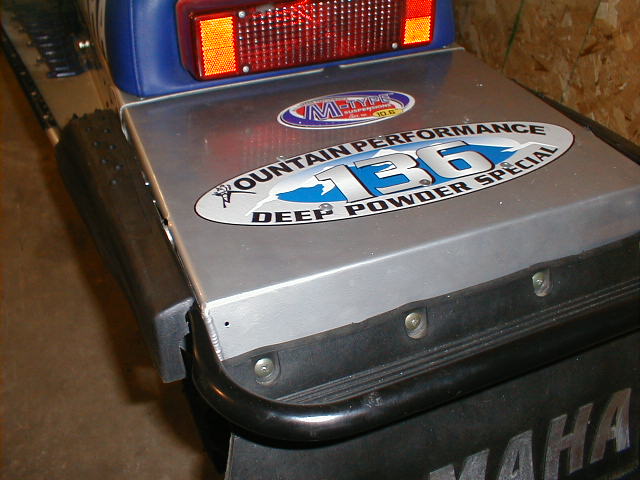
23) Remove the 4 blind nuts from the OEM plastic rear cover and install on the new hose covers.
24) Some 141/144” extensions have 2 rear-mounting holes for the hose cover. If there are 2 holes USE THE TOP HOLE FOR CROSS COUNTRY KITS.
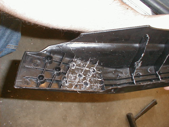
25) Remove the plastic ribbing on the inside front of each hose cover as shown in below. Use care and don’t cut through the cover, juts remove the ribbing making the cover flat. This will provide extra clearance for the rubber hose.
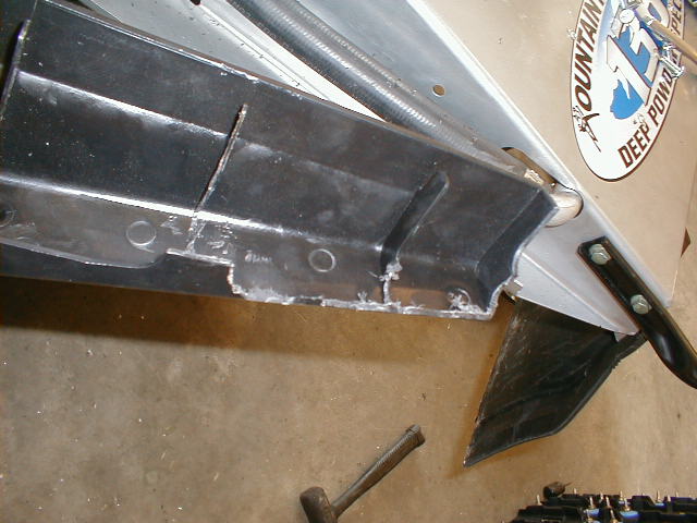
26) Cut the inside rear of each cover so that it will clear the heat exchanger tube and the bumper bolts. See Fig 2F. Note: The cover extends over the top of the extension. TEST FIT THE COVER. CHECK WHERE IT IS HITTING AND REMOVE MATERIAL AS REQUIRED. DON’T REMOVE TOO MUCH AT ONE TIME.
27) Trim an additional ½” to ¾” of hose from the SHORT end of the hose. This will provide additional clearance between the hose and the hose cover.
28) Trim from the LONG end of the hose as required.
29) Install the hoses. The adjuster on the REAR clamp should be on the BOTTOM of the hose. The adjuster on the FRONT clamp should be to the REAR of the hose. NOTE: The hose will be difficult to push onto the running board exchangers on Vipers and SRX. Use Carb cleaner to soften the hose. This hose is designed to stretch. Be patient, it works!
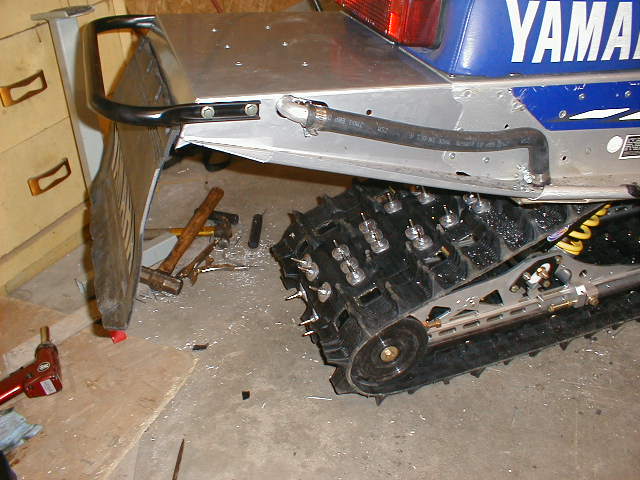
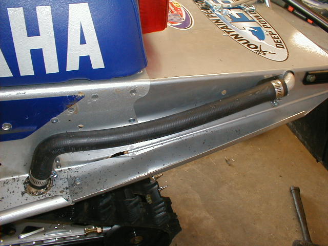
30) Install the hose covers. The covers will sit on top of the black outside rear bracket gussets (except on 141 installations)
31) Reinstall the seat. Don’t forget to connect the taillight wire.
INSTALLING THE M10-136 WITH 1 1/4 STUDDED TRACK AND 8 TOOTH DRIVERS
Basically the M10 -136 is installed the same as the 121" except for a few minor locations changes the steps – click this link for step by step install of the M10 121". Please insert information below in place of the steps as noted.
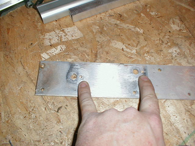
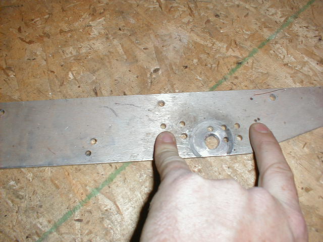
In place of Step 14, DO NOT drill through the tunnel for the main (2) 3/8" dia mounting holes for the front torque arm location. Instead use the (2) 3/16" hole straight back from the 3/8"dia holes approximately 1/2" center to center on your mounting plate. These will be your new location for the torque arm for a 136" application. See Pic Below.
In place of Step 15,16 and 17, we will be adding a lowering kit for mounting a longer m-10 in a tapered tunnel. To mount the kit follow the directions below.
1) Install new upper shaft provided in kit into rear arm.
2) Re-install upper idler wheels (2001 model wheel [615-9030-80] not included in kit), making sure the snap ring is facing the inside of the M-10.
3) Install upper rear spacer included in kit.
4) Bolt lowering bracket to ends of rear shaft with 7/16” x 1 ¼” bolt with lock washer with red loctite. See assembly in picture.
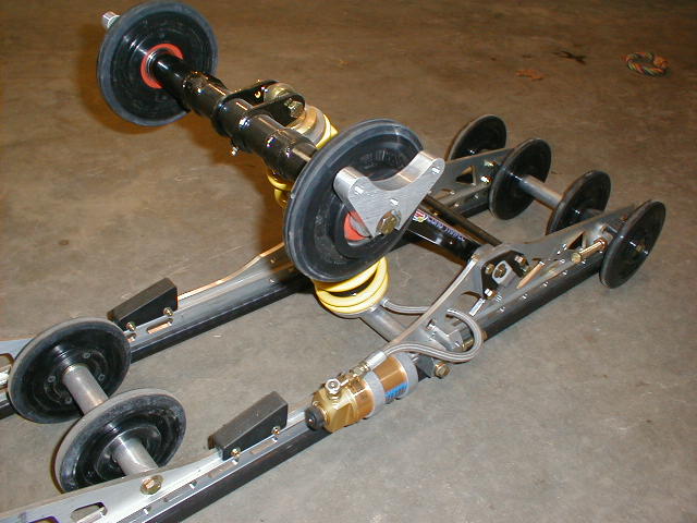
5) When tightening the 7/16 bolts, be sure to lower arms to ground to hold Bracket.
Square side to side and torque to 40 ft lbs. (see diagram)
6) Looking at the rear of tunnel support plate, there are two sets of holes. (see diagram) You will need to use the upper set of holes if the tunnel is flat or no taper at rear of tunnel. If your tunnel is tilted or tapered at the rear, you need to use the lower set of holes. The reason for two sets of holes: If there is not enough clearance with the top set, move to the lower set of holes. (Check both sets of holes for track clearance before drilling any holes.)
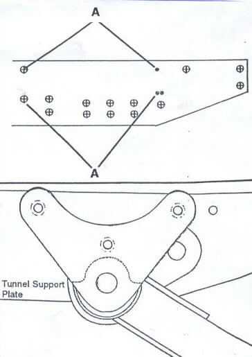
7) After selecting the set of holes, drill the two holes marked with A to 5/16”, center punch the top middle, then drill to 5/16” hole. Do the same on both sides.
8) Insert arm in the tunnel and line up bracket with holes drilled earlier using 5/16” x 1” bolt with 5/16” lock washer, flat washer and red loctite. Bolt into place and torque to 18 ft lbs.
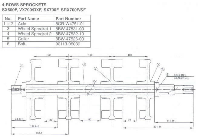
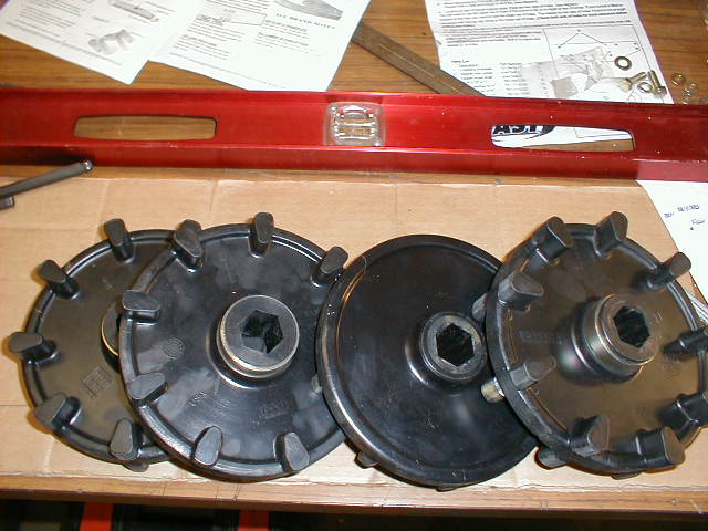
You will have to have the 9 tooth drivers removed and the new drivers pressed back on the drive axel per Yamaha service manual specs. Shown below is the 2001 SXR spec.
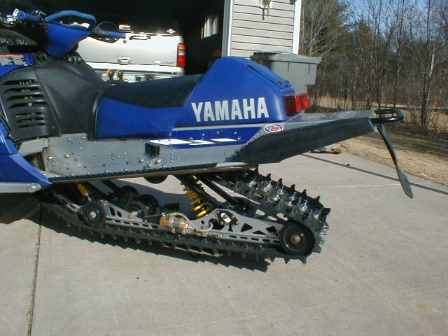
Replace drive axel and all other track and suspension components in the same fashion as was removed per removal Procedure for Replacing your Track. Once New track is in place follow suspension install instruction for remaining of the M10 121". Don't forget to refill your coolant. Enjoy your new Cross Country 136 sled.
Totallyamaha.com would like to thank Mac at Mountain Performance for all his help and his great sponsorship of the site and Brian at Fast Inc for all the help on the M-10 136" layout.
|
|
|
Totallyamaha is not responsible for any damages that these modifications may cause to your vehicle; any modifications are your responsibility if you choose to do so. We are providing information ONLY. Some of these modifications may VOID your warranty and that is your responsibility to look into. The Totallyamaha users have passed along most of the information found on this site. If you have any questions or concerns about anything on this site talk to your dealer before using any of the information. Totallyamaha will not be liable for any damages or personal injury from any modification performed from this site.
Please let us know if you have anything to add to this page to help out other Yamaha owners. For addition to this page Email webmaster@totallyamaha.com
![]()